Angular position inductive sensor

A sensor and inductive technology, applied in the direction of converting sensor output, instruments, and using electric/magnetic devices to transfer sensing components, etc., can solve problems such as high cost and power consumption

Active Publication Date: 2008-03-05
DIEHL METERING
View PDF0 Cites 36 Cited by
  • Summary
  • Abstract
  • Description
  • Claims
  • Application Information

AI Technical Summary

Problems solved by technology

Inductive sensors have the disadvantage of relatively high cost and power consumption

Method used


Image

  • Angular position inductive sensor
  • Angular position inductive sensor

Examples


Embodiment Construction

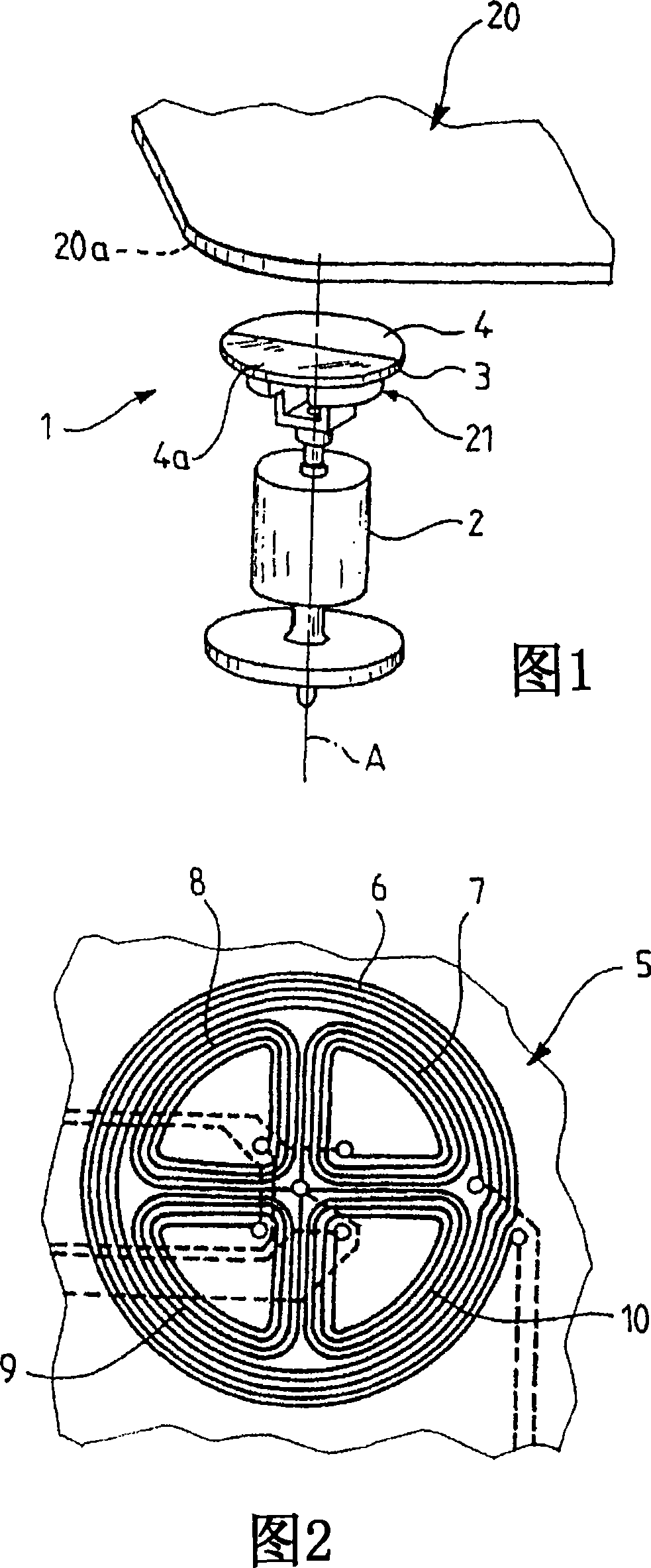
[0026] Referring to FIG. 1 , there is shown a rotary mobile body 2 which is driven to rotate about its axis of rotation A by, for example, a flow of liquid (not shown). The inductive angle sensor 1 includes a stator 20 and a rotor 21 . The stator 20 and the rotor 21 are angularly movable along the axis A relative to each other. It should be noted that the use of the term stator does not imply that the stator 20 has a fixed orientation.

[0027] The rotor 21 includes a rotating disk 3 . The rotary disk 3 is arranged on the rotary moving body 2 so that the rotary disk 3 as a whole rotates along the axis A of the rotary moving body 2 . The flat surface 4 of the disk 3 opposite the rotationally mobile body 2 is partially metallized. For example, half the disc 4a is metallized.

[0028] The stator 20 includes a printed circuit 5 (Fig. 2). The printed circuit 5 is arranged on the right next to the disc 3 and substantially parallel to the surface 4 .

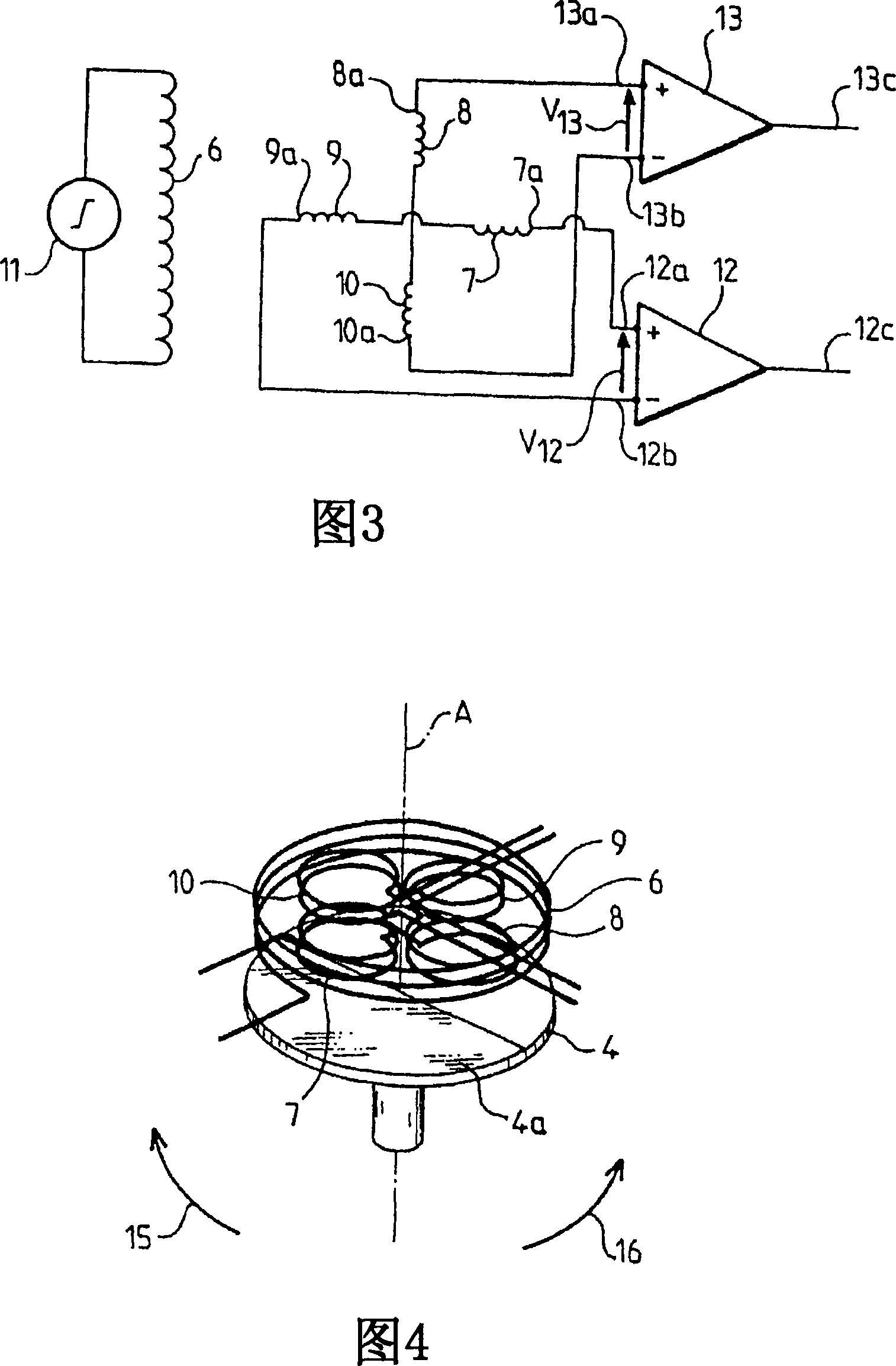
[0029] Referring to Figur...


PUM


Abstract

The invention concerns an angular position inductive sensor, comprising a partly metallized disc mobile in rotation about its axis of revolution and a stator including a primary coil and a plurality of secondary coils, said secondary coils being arranged in pairs substantially symmetrical relative to said axis of revolution, so as to form one or more pair(s) of secondary coils, said secondary coils of each pair being connected to one another in series and in phase-opposition relative to one another and to the terminals of measuring means adapted to generate an output signal based on the voltage at the terminals of said pair.

Description

technical field [0001] The object of the present invention is an inductive angle sensor. Background technique [0002] Typically a mechanical part that rotates based on the flow of the liquid is used in order to measure the flow rate. In general, an angular position sensor detects the rate of rotation of a rotating component in order to allow electrical processing of the information. Although not limited thereto, the invention is particularly suited for this application. [0003] Several schemes are known for detecting angular positions. [0004] The first approach uses magnetic sensors. Its rotating part is fitted with a small permanent magnet whose magnetic field causes electrical contact with a Reed ampoule placed nearby. Thus, switching of this electrical contact represents the flow of liquid. For example, some sensors rely on several ampoules to enable them to detect the direction of rotation of the rotating part and thus the direction of flow of the liquid. These...

Claims


Application Information

Patent Timeline
Patent Type & Authority Applications(China)
IPC IPC(8): G01D5/22
CPCG01D5/2053G01P3/488
Inventor 盖·巴赫伯纳德·多克维勒
Owner DIEHL METERING
Why Eureka
Try Eureka