Steel truss of through bridge

A steel truss and truss technology, applied in truss bridges, bridges, bridge forms, etc., can solve problems such as excessive material consumption, difficulty in production, construction and post-maintenance, and achieve low cost, easy processing and installation, and reduced lateral amplitude. Effect

Inactive Publication Date: 2008-03-12
SOUTHWEST JIAOTONG UNIV
View PDF4 Cites 6 Cited by
  • Summary
  • Abstract
  • Description
  • Claims
  • Application Information

AI Technical Summary

Problems solved by technology

The disadvantages of these two methods are: the material consumption is too large, and the production, construction and post-maintenance are difficult

Method used


Image

  • Steel truss of through bridge

Examples


Embodiment

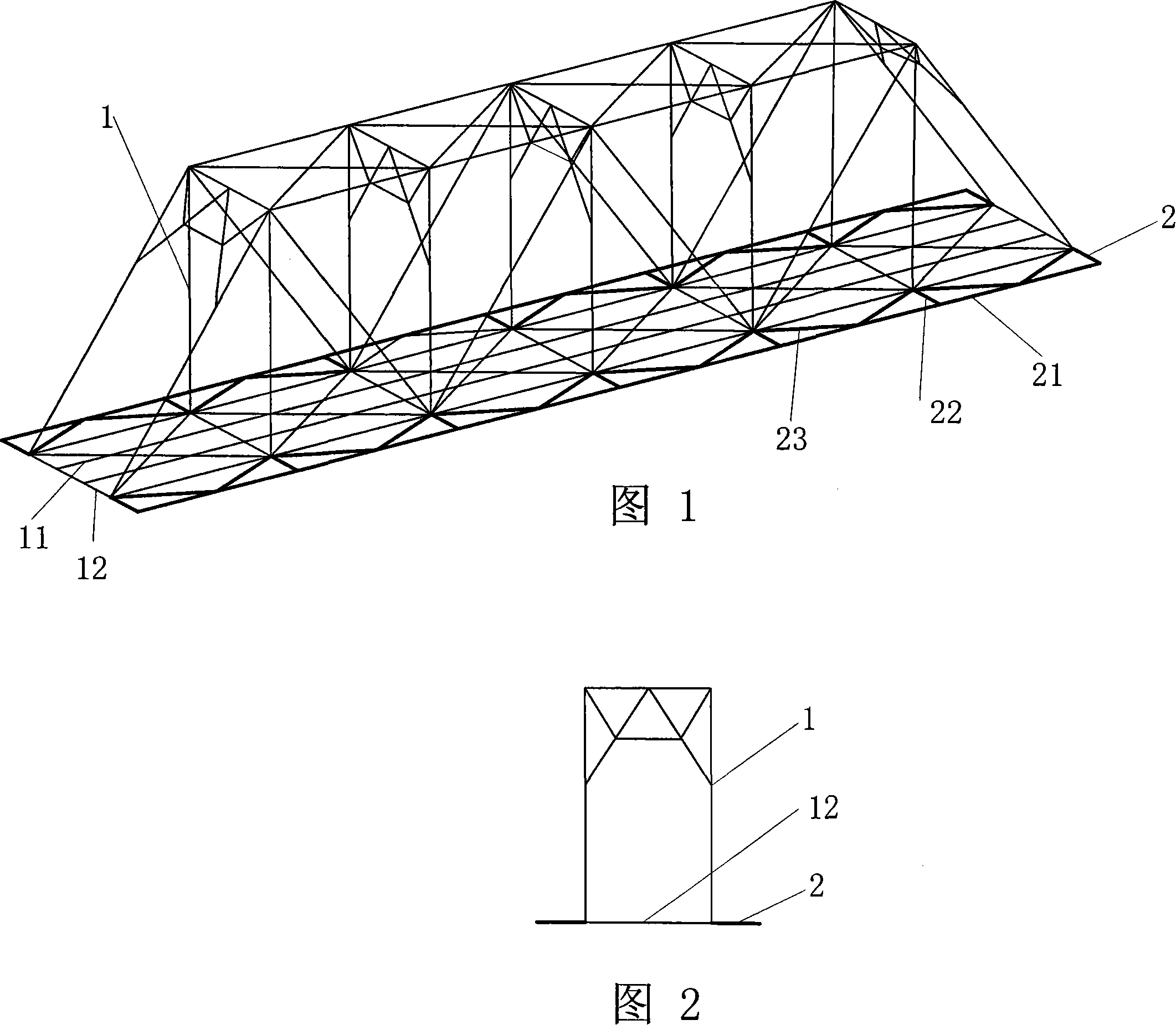
[0014] Figures 1 and 2 show that a specific embodiment of the present invention is: a steel truss of an underpass bridge, including a truss 1 with a rectangular cross section. Both sides of the bottom of the truss 1 are fixedly connected with a plane bracket 2 of steel structure, and the plane bracket 2 is on the same plane as the bottom of the truss 1 .

[0015] The planar bracket 2 is composed of: the end of the bottom beam 12 of the truss 1 is extended to connect the cross brace 22, the chord 21 connected with the cross brace 22 and parallel to the longitudinal beam 11, and several chords 21 and the cross brace 22 constitute There are oblique braces 23 connected obliquely in the rectangular internodes, and the chords 21 , cross braces 22 and diagonal braces 23 form the plane bracket 2 .

[0016] Obviously, in practical implementation, the beam 12 and the cross brace 22 of the present invention can be an integrated structure composed of a steel piece.

[0017] There are one...


PUM


Abstract

A bottom-supported bridge steel truss comprises a truss (1) that is connected with a steel structural plane bracket (2) on both sides of the bottom of the truss; the plane bracket (2) is in the same plane with the bottom of the truss (1). The steel truss structure can increase transversal rigidity of steel girder bridges, but lower transversal amplitude of vibration; and meanwhile, the structure has advantages of easy assembly and relatively low cost.

Description

technical field [0001] The present invention relates to steel trusses for under-supported bridges. Background technique [0002] The under-supported steel truss is used as the load-bearing structure of the bridge. The cross-section of the steel truss is rectangular, and the bridge deck is located at the bottom of the steel truss, so the bottom of the truss is the main force-bearing member. The lateral vibration amplitude of long-span, fast or high-speed line bridges (that is, the left and right swing of the bridge) is relatively large. In order to increase the lateral stiffness of the truss and reduce the lateral vibration amplitude of the bridge, it is usually necessary to: (1) increase the section of the member, (2) Increase the lateral distance (width) of the entire truss. The disadvantages of these two methods are: the material consumption is too large, and the production, construction and post-maintenance are difficult. Contents of the invention [0003] The object ...

Claims


Application Information

Patent Timeline
Patent Type & Authority Applications(China)
IPC IPC(8): E01D6/00
Inventor 郑凯锋李荣昌吴臻旺胡绘新
Owner SOUTHWEST JIAOTONG UNIV
Why Eureka
Try Eureka