Electric fuel pump and method for manufacturing the same
A fuel pump and fuel channel technology, which is applied to fuel injection devices, charging systems, engine components, etc., can solve problems such as large size of fuel pumps
- Summary
- Abstract
- Description
- Claims
- Application Information
AI Technical Summary
Problems solved by technology
Method used
Image

Examples
no. 1 example
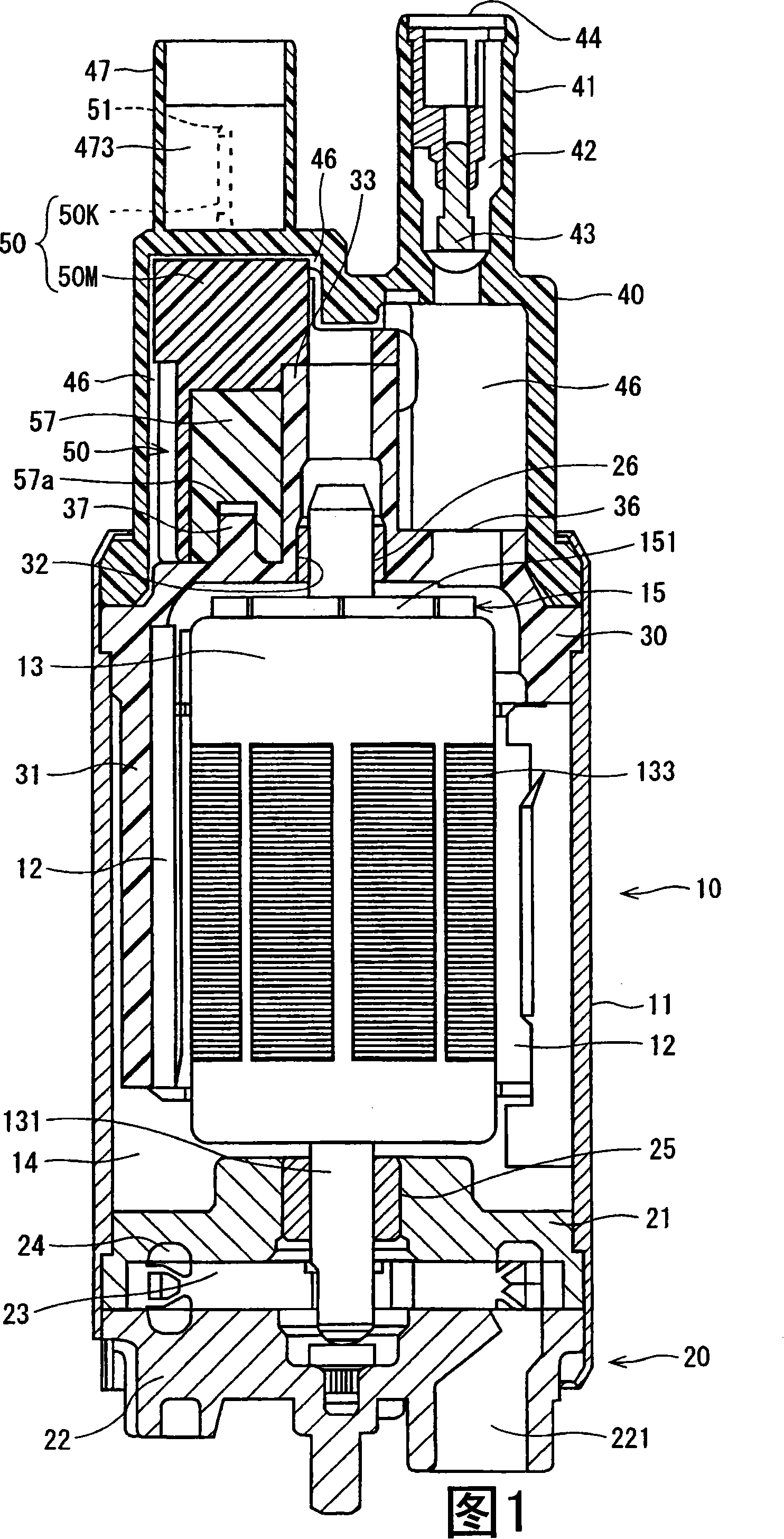
[0030] A fuel pump according to one embodiment is described below with reference to FIGS. 1 to 10C.
[0031] The fuel pump shown in FIG. 1 is an in-tank pump installed in, for example, a fuel tank of an automobile. Accordingly, the fuel pump is completely immersed in the fuel. The fuel pump supplies fuel from the fuel tank to the engine. The fuel pumped by the fuel pump is a fuel containing highly conductive components such as high-density alcohol petroleum fuel mixture, bio-alcohol, and 100% alcohol fuel.
[0032] As follows, the structure of the fuel pump is described with reference to FIG. 1 . The fuel pump comprises a motor part 10 and a pump part 20 which is driven by the motor part 10 to increase the pressure of the pumped fuel.
[0033] The motor section 10 includes a DC motor having brushes. The fuel pump comprises a substantially cylindrical housing 11 . The housing 11 has an inner edge to which permanent magnets 12 are arranged annularly in the circumferential d...
no. 2 example
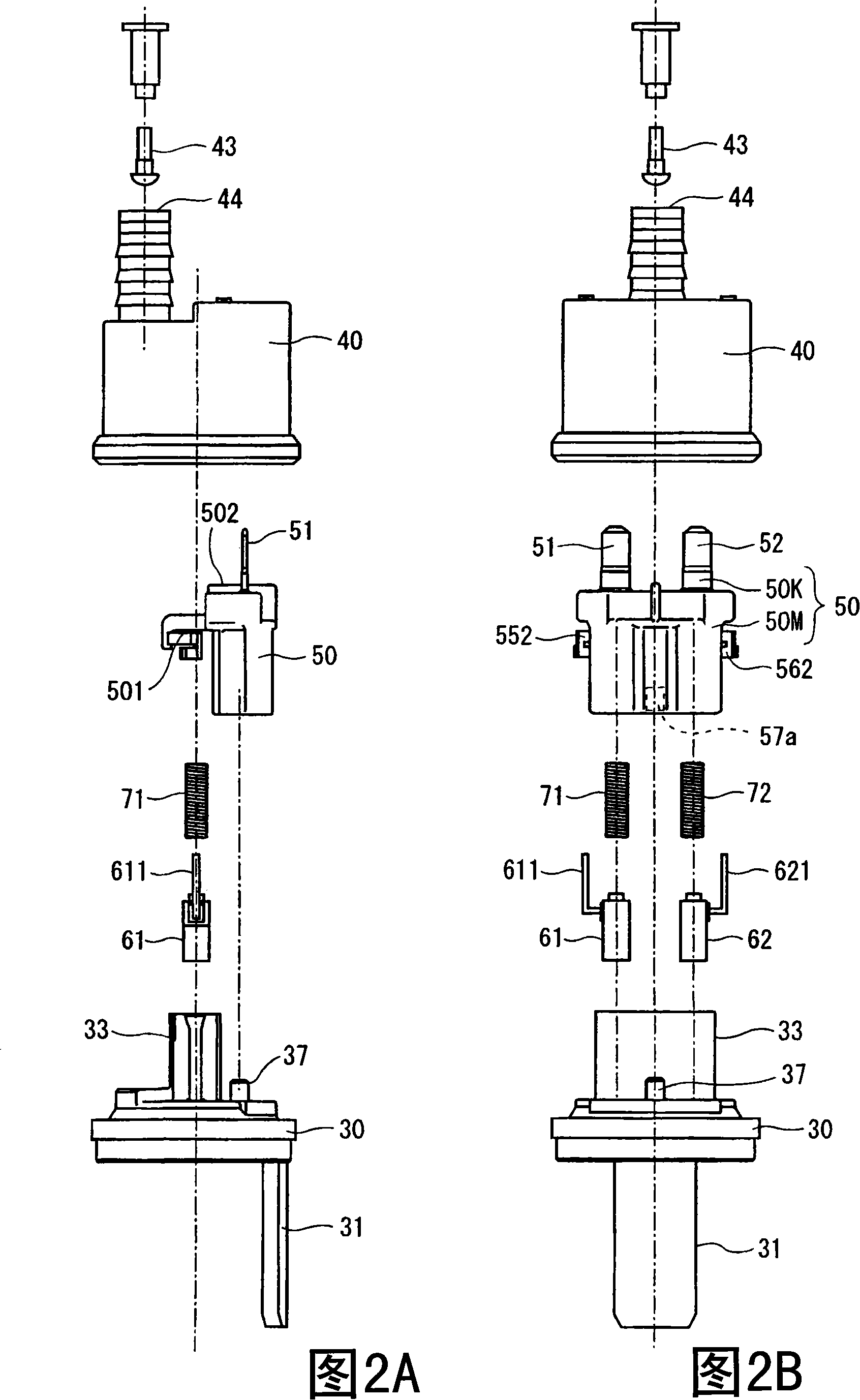
[0100] A fuel pump of a second embodiment is described with reference to FIGS. 11 to 13D.
[0101] As shown in FIGS. 12A, 12B, the molded body 50 is constructed from a molded portion 50M and an assembled body 50K, similarly to the first embodiment. In this embodiment, the discharge side cover 40 may not be provided with the connector housing 47 (see FIG. 1 ).
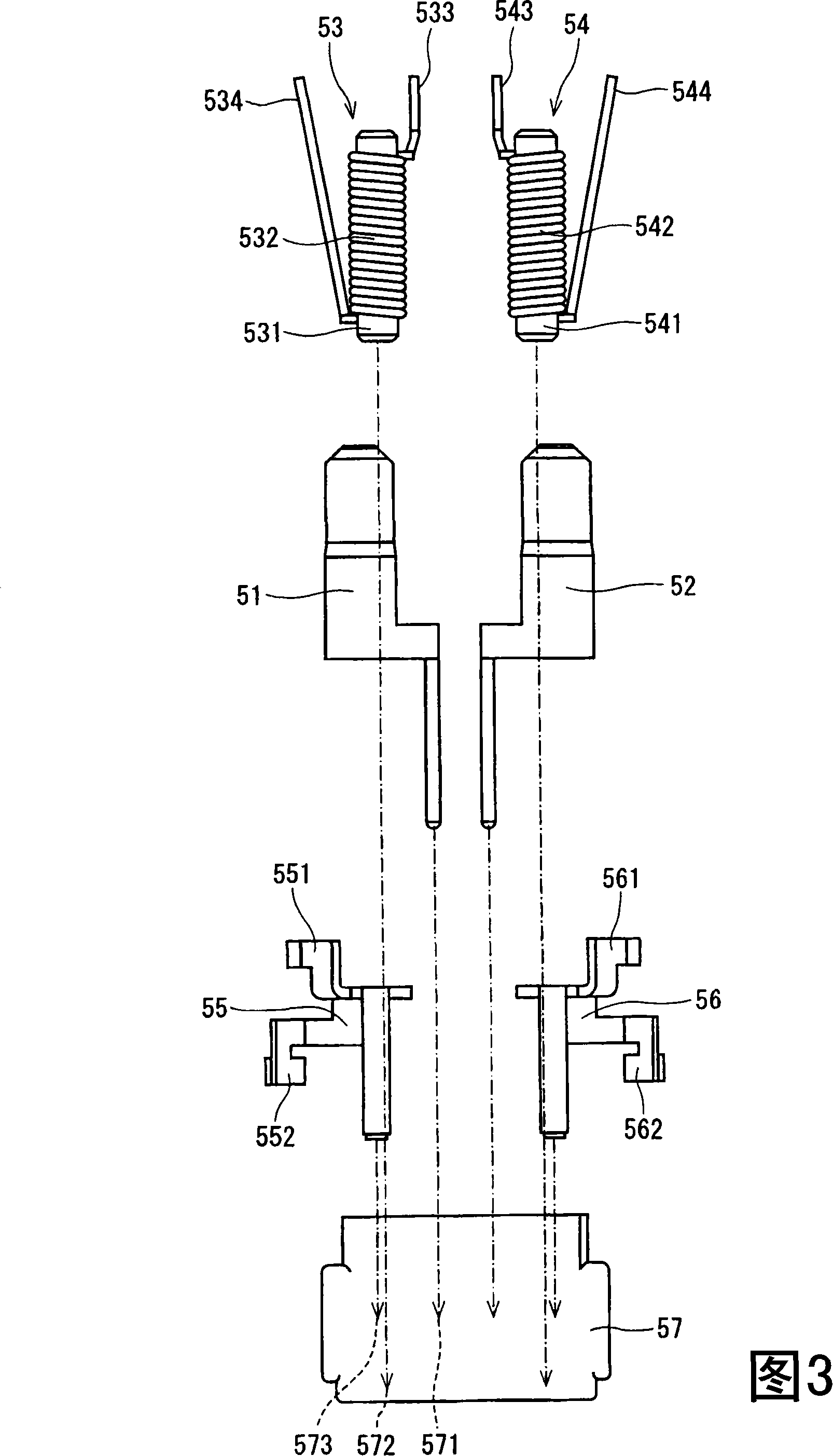
[0102] In the structure of the embodiment, the external connection terminal 51 on the positive electrode side and the external connection terminal 52 on the negative electrode side are also mounted to the holder 57 of the insulator and are also resin molded. Therefore, it is also possible to reduce such an area compared with the conventional structure in which the external connection terminals 51, 52, choke coils 53, 54, and brush terminals 55, 56 are mounted only on the holder 57 and are not resin molded, That is to say through this area, the external connection terminals 51 , 52 , the choke coils 53 , 54 and the brus...
PUM
 Abstract
Description
Claims
Application Information
 - R&D
- Intellectual Property
- Life Sciences
- Materials
- Tech Scout
- Unparalleled Data Quality
- Higher Quality Content
- 60% Fewer Hallucinations
Browse by: Latest US Patents, China's latest patents, Technical Efficacy Thesaurus, Application Domain, Technology Topic, Popular Technical Reports.
© 2025 PatSnap. All rights reserved.Legal|Privacy policy|Modern Slavery Act Transparency Statement|Sitemap|About US| Contact US: help@patsnap.com