Laser bias current current limiting circuit

A bias current and current limiting circuit technology, applied in lasers, laser parts, semiconductor lasers, etc., can solve the problems of different forward working voltages and inaccurate results, and achieve the effect of preventing laser damage.

Active Publication Date: 2008-03-12
ZTE CORP
View PDF0 Cites 8 Cited by
  • Summary
  • Abstract
  • Description
  • Claims
  • Application Information

AI Technical Summary

Problems solved by technology

[0009] Therefore, the current limiting circuit can play the role of current limiting, and at the same time, it will not turn off the laser while limiting the current, which will affect the business. However, its disadvantage is that different manufacturers and different types of lasers have different forward working voltages, and the same current limiting circuit is used. Resistor value, the result obtained is inaccurate

Method used


Image

  • Laser bias current current limiting circuit
  • Laser bias current current limiting circuit
  • Laser bias current current limiting circuit

Examples


Embodiment Construction

[0024] The preferred embodiments of the present invention will be described below in conjunction with the accompanying drawings. It should be understood that the preferred embodiments described here are only used to illustrate and explain the present invention, and are not intended to limit the present invention.

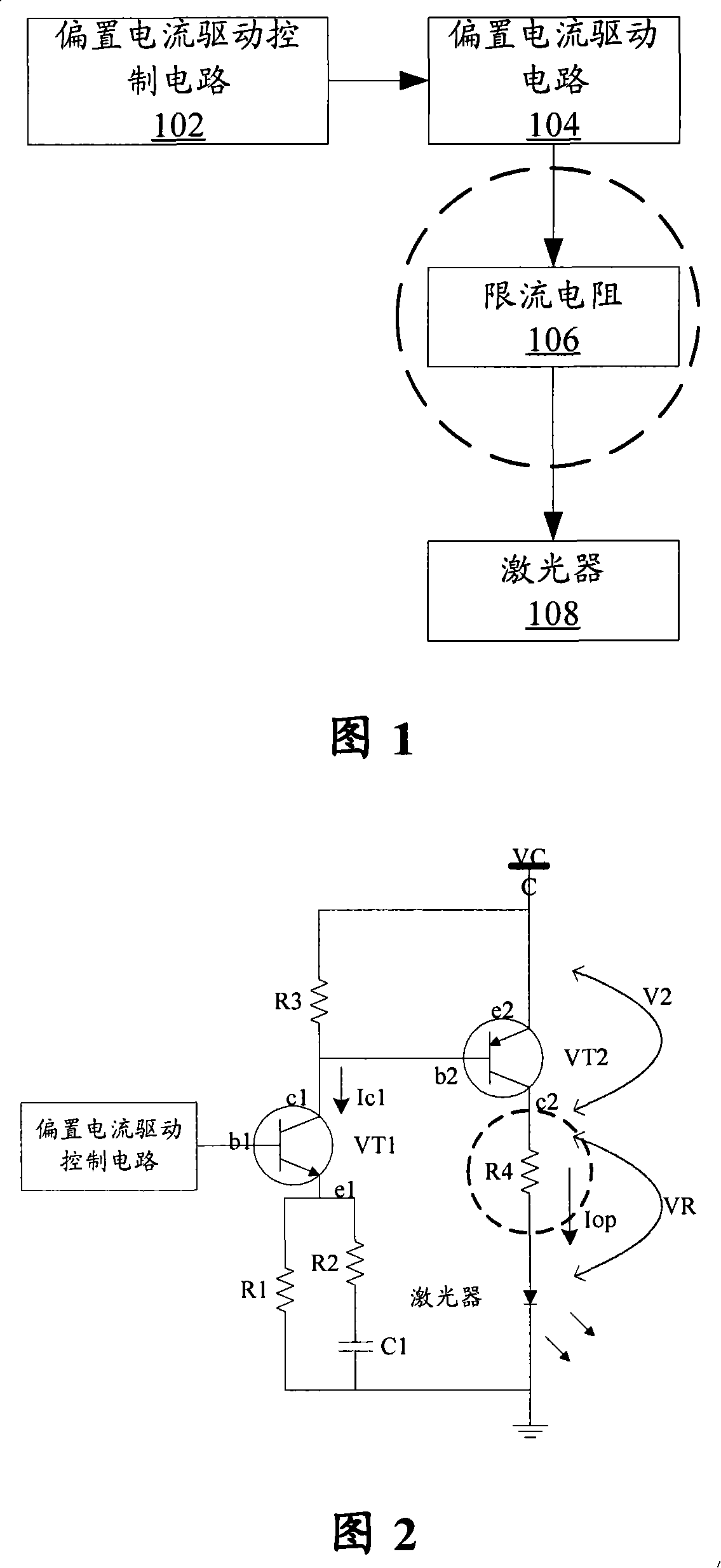
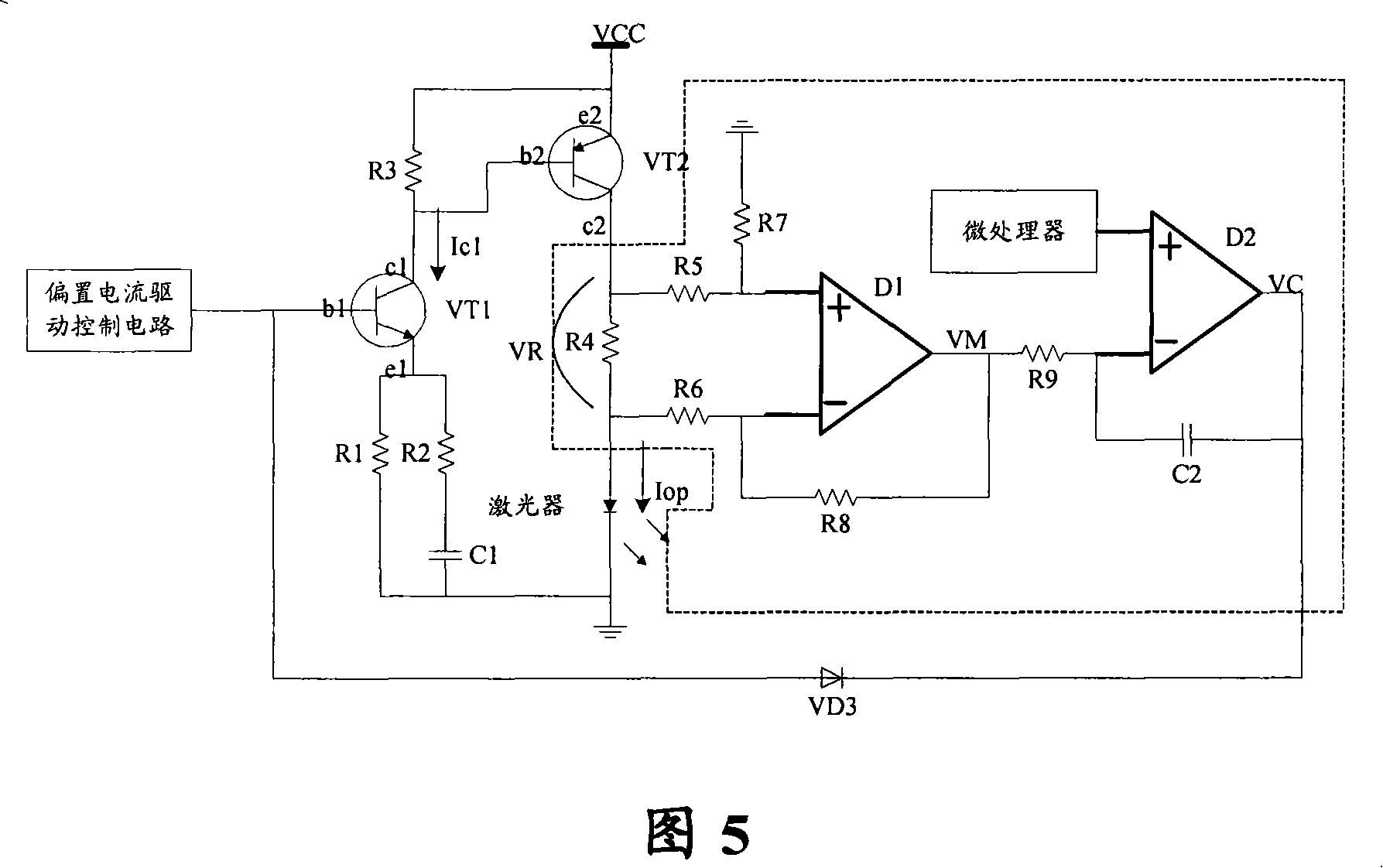
[0025] FIG. 4 is a structural block diagram of a laser bias current limiting circuit according to the present invention. As shown in FIG. 4 , like the prior art, the laser bias current limiting circuit of the present invention also includes a bias current drive control circuit 402 and a bias current drive circuit 404 . In addition, the current limiting circuit of the laser bias current of the present invention also includes: a sampling resistor 406, which is connected in series between the bias current drive circuit 404 and the laser 408, and is connected to the input end of the proportional amplification circuit 410; Circuit 410, its output terminal is connected to...


PUM


Abstract

The invention discloses a current limiting circuit of laser bias current, which comprises a bias current driving control circuit, a bias current driving circuit, a sampling resistance which is connected in series between the bias current drive circuit and the laser and also connected to an output end of a proportional amplifying circuit; a proportional amplifier, the output end is connected with the cathode of a comparator, which is used to change the current of the flowing sampling resistance into the corresponding voltage; the comparator, the anode is connected with a reference voltage, the output end is connected to a start circuit for comparing the cathode and the anode; the start circuit, the output is connected with the input end of the comparator, the output end is connected with a bias current driving control circuit for turn on or off the current limiting circuit according to the input from the input end. Therefore, the current limiting circuit of the laser bias current adopting the invention can prevent the damage to the laser caused by too large bias current effectively happening.

Description

technical field [0001] The invention relates to a current limiting circuit for laser bias current. Background technique [0002] The laser is the main component of the optical transmitter, and it is also a vulnerable component. Therefore, it is required to work within a certain current range. If the current is too large, its life will be shortened, and the laser will be damaged if it is serious. Therefore, current limiting measures must be added. In the laser bias circuit, the maximum current of the laser should be used as the current limit threshold, and the current provided to the laser should not exceed the threshold current during use. The traditional laser bias circuit achieves current limiting by adding a current limiting resistor. [0003] Figure 1 shows a conventional laser bias current circuit. As shown in FIG. 1 , a traditional laser bias current circuit includes four parts, a bias current drive control circuit 102 , a bias current drive circuit 104 , a current l...

Claims


Application Information

Patent Timeline
Patent Type & Authority Applications(China)
IPC IPC(8): H01S5/042H01S3/09
Inventor 任之良葛超王加莹张鹏
Owner ZTE CORP
Why Eureka
Try Eureka