Mud scraping device

A mud scraper and driving device technology, applied in public buildings, gymnasiums, building types, etc., can solve the problems of resistance, limited cleaning effect, inconvenience, etc., to reduce the use cost, reduce the power burden, and avoid environmental pollution Effect

Inactive Publication Date: 2008-03-19
黄志彬 +1
View PDF0 Cites 3 Cited by
  • Summary
  • Abstract
  • Description
  • Claims
  • Application Information

AI Technical Summary

Problems solved by technology

[0005] The actuation mode of the mud scraping device 60 is mainly to drive the mud scraper 62 to move relative to the bottom of the water tank 50 through the chain 61, and then to concentrate and clean the mud 70 deposited on the bottom of the water tank 50 in a fixed direction, and because the mud scraper 621 is It is a straight end face, so each mud scraper 62 is to be in contact with silt 70 slightly at 90 degrees, and carries out the cleaning of silt 70 by the mode of pushing, yet this kind of pushing way will not only be able to scrape mud Resistance is caused when the plate 62 moves, which relatively increases the load or damage of the motor driving the chain 61 or deforms or damages the mud scraper 62 due to pushing, and the mud scraper 621 with a flat end face carries out sediment 70 The cleaning effect is limited, so the sediment at the bottom of the water tank 50 cannot be completely removed, and the operating efficiency of the scraper 62 is relatively reduced. This will not only increase the cost of using the scraper 62, but the damaged scraper 62 will easily cause garbage and environmental pollution issues
[0006] This shows that the above-mentioned existing mud scraping device obviously still has inconvenience and defects in structure and use, and needs to be further improved urgently
In order to solve the above-mentioned problems, the relevant manufacturers have tried their best to find a solution, but no suitable design has been developed for a long time, and the general products do not have a suitable structure to solve the above-mentioned problems. This is obviously related. The problem that the industry is eager to solve

Method used


Image

  • Mud scraping device
  • Mud scraping device
  • Mud scraping device

Examples


Embodiment Construction

[0050] In order to further explain the technical means and effects of the present invention to achieve the intended purpose of the invention, the specific implementation, structure, features and effects of the mud scraping device proposed in accordance with the present invention will be given below with reference to the drawings and preferred embodiments. The detailed description is as follows.

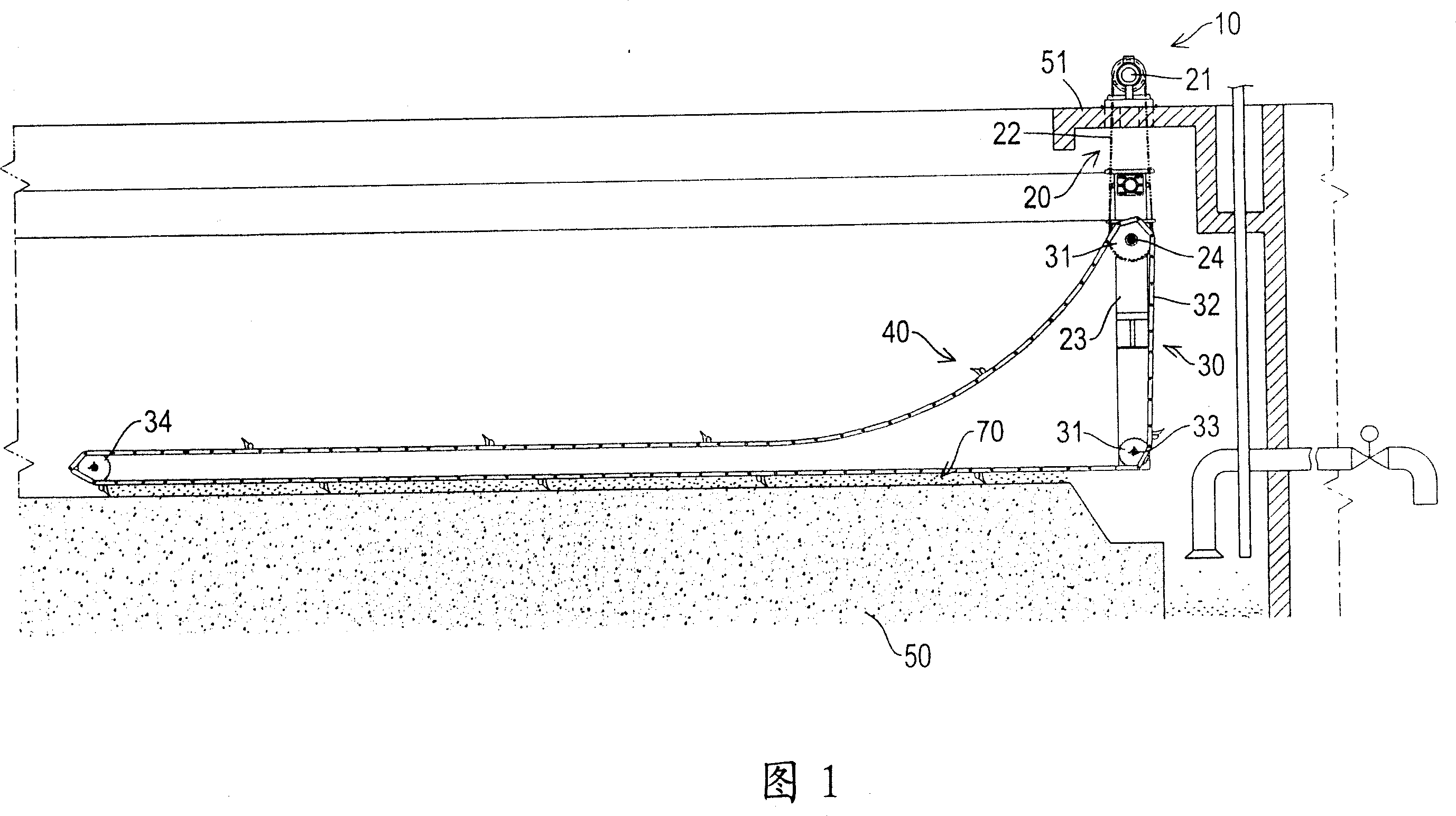
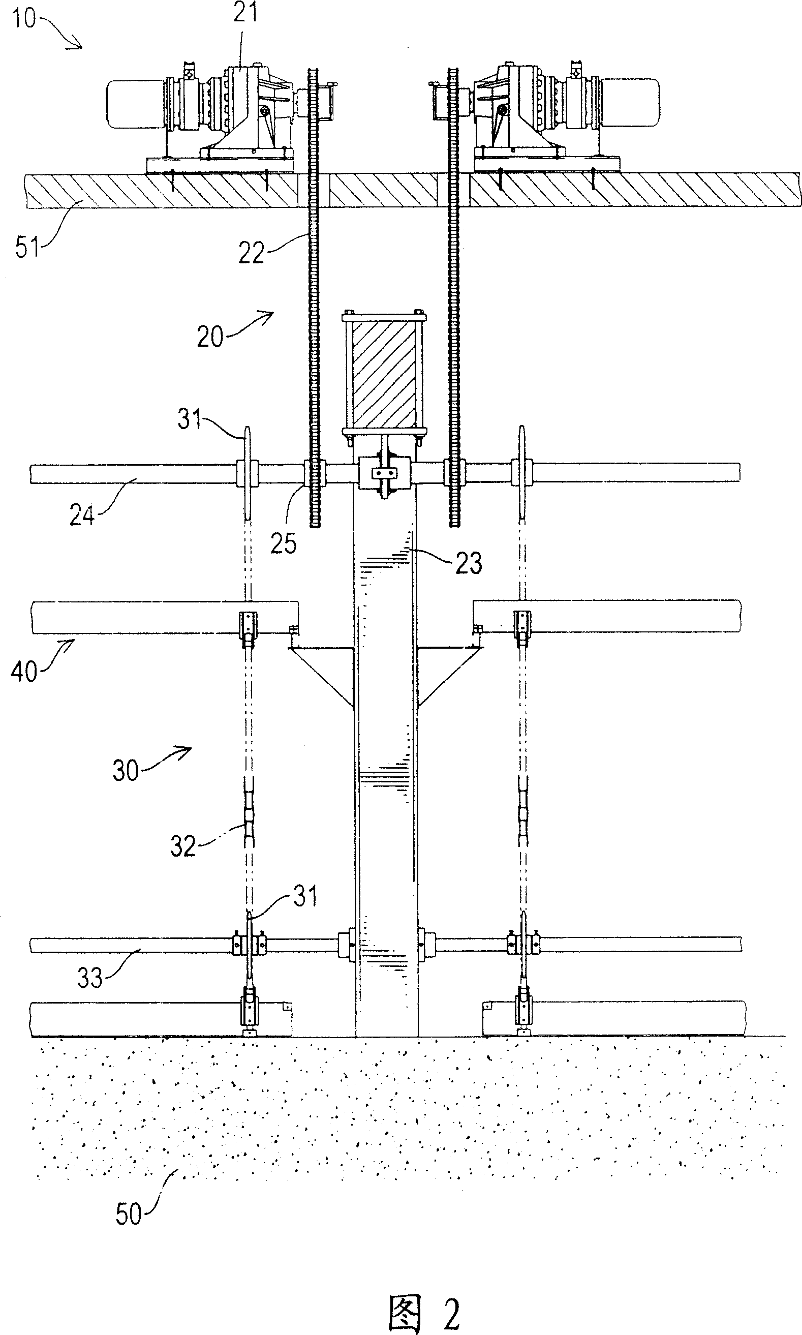
[0051] The present invention mainly provides a mud scraping device 10. Please refer to Figs. 1 to 2 in conjunction. It can be seen from the figures that the mud scraping device 10 of the present invention is combined with a water tank 50 and includes:

[0052] A drive device 20, the drive device 20 includes a drive motor 21, a drive chain 22, a support column 23, a main shaft 24 and a transmission sprocket 25, wherein the drive motor 21 is installed by a support plate 51 It is located above the water tank 50, and the drive chain 22 is combined with the drive motor 21 to extend in the wate...


PUM


Abstract

The invention relates to a mud scraping device, and comprises a driving device, the driving device is provided with a driving motor, a driving chain, a support column, a principal axis and a drive sprocket wheel, the driving chain is connected with the motor, the support column is arranged at the bottom of a water tank relative to the location of the driving chain, the principal axis is arranged on the support column, the driving chain is arranged on the principal axis and connected with the driving chain; a slave device combined with the driving device is provided with two slave sprocket wheels, a slave chain and a slave axis, wherein, the slave sprocket wheel is arranged on the principal axis and combined with the slave chain, the slave chain is penetrated on the support column, the other slave chain is arranged on the slave axis; and a plurality of slave chains combined with the slave chain, and thereby, the invention provides a mud scraping device with high-efficient mud clearing effect.

Description

Technical field [0001] The invention relates to a mud scraping device in the technical field of mud and sand removal, in particular to a mud scraping device that can conveniently scrape the mud and sand at the bottom of a water tank. Background technique [0002] In order to prevent sedimentation or impurities from depositing on the bottom of the sink or pool, which will reduce the water removal capacity of the sink and affect the water quality, the mud scraper is generally used to remove the mud at the bottom of the sink. [0003] As shown in FIG. 7, the existing mud scraping device 80 is installed in the water tank 50. It mainly includes an endless chain 81, and a plurality of scrapers 82 are installed transversely on the chain 81. The drive motor combined with the chain 81 is driven to perform the cleaning action. The early mud scraping device 80 used wood such as mahogany or Nanyang camphor wood as the scraper 82. In use, it is not only necessary to preservatively treat the w...

Claims


Application Information

Patent Timeline
Patent Type & Authority Applications(China)
IPC IPC(8): E04H4/16
Inventor 魏青迪
Owner 黄志彬
Why Eureka
Try Eureka