LED road lamp

A technology for LED street lamps and substrates, which is applied in the loss prevention measures of lighting devices, cooling/heating devices of lighting devices, outdoor lighting, etc., can solve the problem of inability to adapt to the long-term working requirements of street lamps, inability to form effective convection, and low air heat transfer coefficient and other problems, to achieve the effect of good heat dissipation, help heat dissipation, and large contact area

Inactive Publication Date: 2008-03-19
珠海泰坦新能源系统有限公司
View PDF0 Cites 1 Cited by
  • Summary
  • Abstract
  • Description
  • Claims
  • Application Information

AI Technical Summary

Problems solved by technology

However, the internal space of the lampshade is closed and limited, and effective convection cannot be formed, and the heat transfer coefficient of the air is low. Therefore, this kind of LED street lamp only dissipates heat from the LED to the heat sink quickly, and dissipates heat from the heat sink to the outside very slowly, so it cannot adapt to street lights. long-term work requirements

Method used


Image

  • LED road lamp
  • LED road lamp

Examples


Embodiment 1

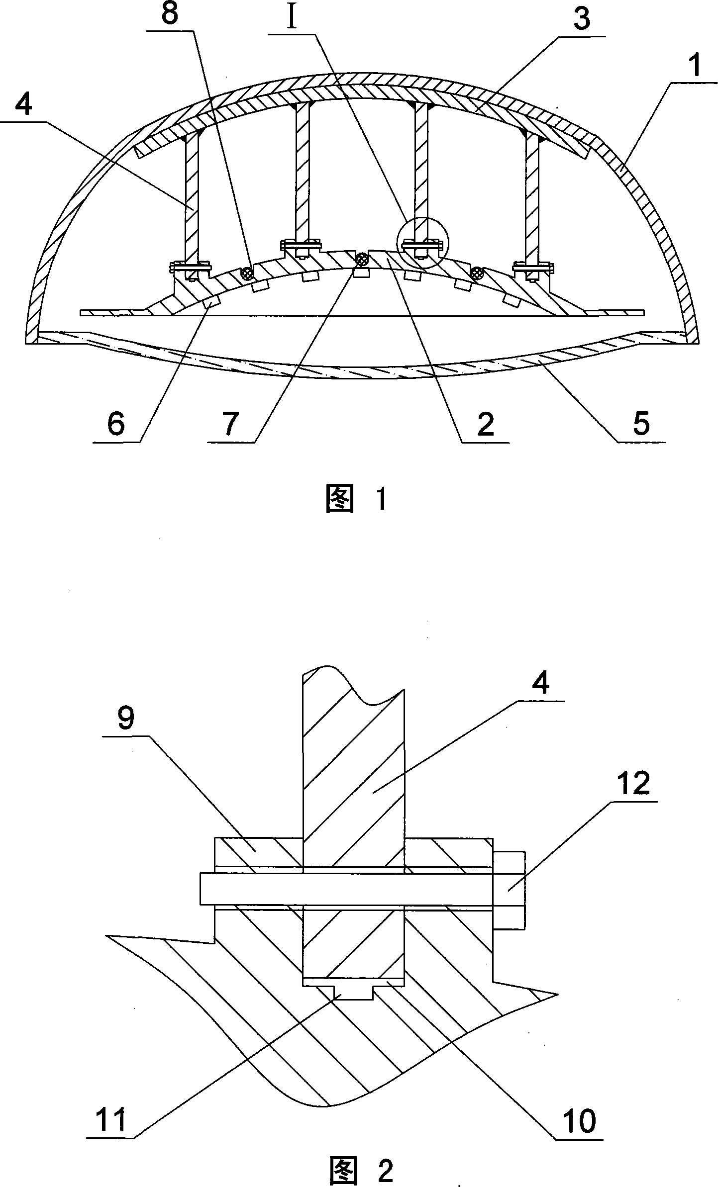
[0027] As shown in Figures 1 and 2, the present invention includes a metal back cover 1, a substrate 2, a heat-conducting back plate 3, several heat-conducting ribs 4, a light-transmitting front cover 5, and several LEDs 6, and several LEDs 6 are mounted on the The front side of the substrate 2 is arranged together with the substrate 2 in the cavity surrounded by the rear cover 1 and the front cover 6. The substrate 2 is inwardly concave, and of course it can also be in other shapes such as outwardly convex , the back side of the substrate 2 is provided with several wire grooves 8 and several convex parts 9, of course, the wire grooves 8 can also be arranged on the front of the substrate 2, and the wires 7 are placed in the wire grooves 8, so that the wires The arrangement is neat and beautiful and easy to identify. The heat-conducting backplane 3 is in close contact with the inner surface of the rear cover 1 and the shapes of the two are compatible. The upper and lower parts o...

Embodiment 2

[0029] As shown in Figure 3, the difference between this embodiment and Embodiment 1 is that the groove 10 is a dovetail groove, and the positioning fastener 12 is not provided in this embodiment, but is fixed by the specific shape of the dovetail groove itself. purpose of positioning.

[0030] The remaining features of this embodiment are the same as those of Embodiment 1.

Embodiment 3

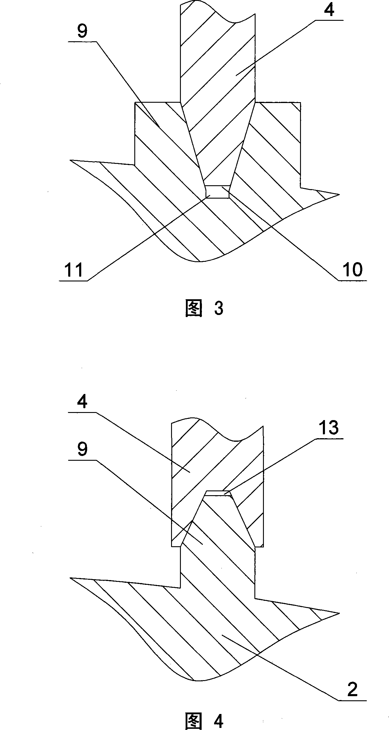
[0032] As shown in Figure 4, the difference between this embodiment and the second embodiment is that: the bottom of the heat conducting rib 4 is provided with an upward groove 13, and the shape of the top of the convex part 9 is adapted to the groove 13 and fixedly arranged In the groove 13, the groove 13 is a dovetail groove, of course, the groove 13 can also be a straight groove, and the thermal conductive glue groove 11 is not provided in this embodiment.

[0033] The other features of this embodiment are the same as those of Embodiment 2.

[0034] The invention has simple structure, convenient installation, high luminous efficiency, good heat dissipation effect and long service life, and is an ideal replacement product for existing street lamps.


PUM


Abstract

The invention discloses an LED street lamp, with the purpose of providing an LED street lamp which has good heat radiation effect and prolongs the service life effectively. The invention comprises a metal rear cover (1), a base plate (2), a non light tight front cover (5) and a plurality of LEDs (6), wherein, a plurality of LEDs (6) are installed on the face side of the base plate (2), and are arranged in the cavity surrounded by the rear cover (1) and the front cover (5) together with the base plate (2), the LED street lamp also comprises a heat conducting back plate (3), a plurality of heat conducting ribs (4), wherein, the back side of the base plate (2) is provided with a plurality of convex sections (9), the heat conducting back plate (3) and the inner surface of the rear cover (1) contact tightly and have adaptive shapes, and the upper part and the lower part of the heat conducting ribs (4) are respectively connected with the back plate (3) and the convex sections (9). The invention can be widely applied to the outdoor illumination field.

Description

technical field [0001] The invention relates to an LED street lamp. Background technique [0002] The energy consumption in the lighting field accounts for about 20% of the entire electric energy, while only 30% of the electric energy of ordinary lighting lamps is used to emit light, and the rest is converted into heat energy and emitted to the outside world. LED is regarded as a cold light source because it generates less heat during operation and has higher luminous efficiency. LED street lights are composed of substrates with LEDs, lenses, and heat dissipation systems. Compared with traditional incandescent and fluorescent lamps, their energy-saving efficiency can reach more than 90%. Since its birth, it has attracted more and more attention from all over the world due to its high efficiency, low consumption, energy saving, environmental protection, and long life. At present, the electricity used for street lighting in my country is close to 250 billion kWh every year. ...

Claims


Application Information

Patent Timeline
Patent Type & Authority Applications(China)
IPC IPC(8): F21V29/00F21V15/02F21V17/00F21S8/00F21W131/103F21Y101/02F21V29/508F21Y115/10
CPCY02B20/72
Inventor 李斯嘉
Owner 珠海泰坦新能源系统有限公司
Why Eureka
Try Eureka