
Equivalent sampling device

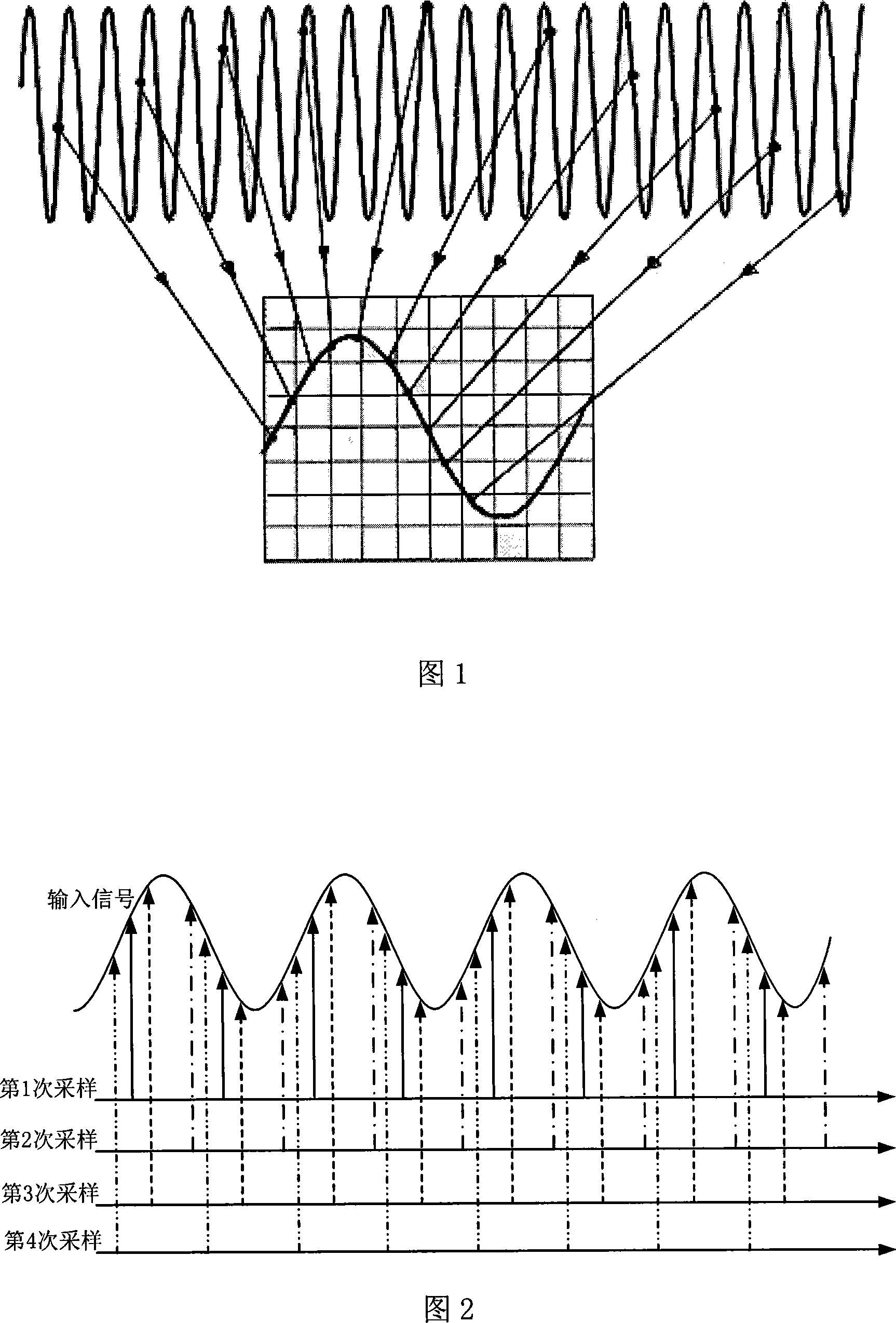
A technology of equivalent sampling and sampling clock, which is applied in measurement devices, instruments, measurement of electrical variables, etc., can solve the problem of difficult to guarantee the reliability of the measurement accuracy circuit, and achieve the effect of easy and simple circuit

Inactive Publication Date: 2008-03-19
UNIV OF ELECTRONICS SCI & TECH OF CHINA
View PDF0 Cites 38 Cited by
  • Summary
  • Abstract
  • Description
  • Claims
  • Application Information

AI Technical Summary

Problems solved by technology

[0014] The time discriminator in random sampling is its key technology. It is used to identify the time difference between the first sampling point clock and the trigger point after the trigger, and the measurement of the time difference often needs to be implemented with more complex peripheral circuits. The measurement Accuracy and circuit reliability are difficult to guarantee

Method used


Image

  • Equivalent sampling device
  • Equivalent sampling device
  • Equivalent sampling device

Examples


Embodiment Construction

[0029] The following describes preferred specific embodiments of the present invention in conjunction with the accompanying drawings. It should be reminded that in the following description, when detailed descriptions of known functions and designs employed may obscure the subject matter of the present invention, these descriptions will be omitted here.

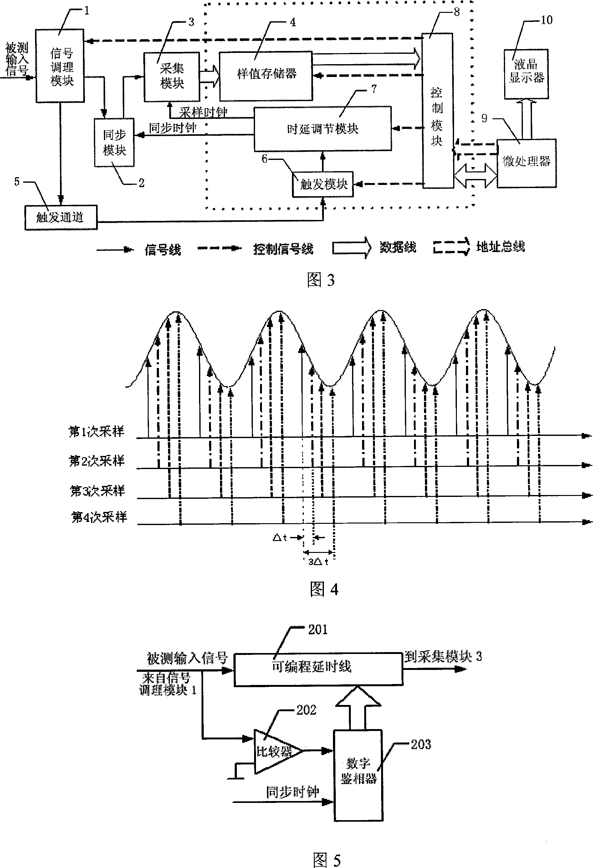
[0030] Fig. 3 is a functional block diagram of a specific embodiment of the equivalent sampling device of the present invention. In the figure, the equivalent sampling device includes a signal conditioning module 1, a synchronization module 2, an acquisition module 3, a sample memory 4, a trigger channel 5, a trigger module 6, a delay adjustment module 7, a control module 8, a microprocessor 9 and a liquid crystal Display 10. Among them, the sample memory 4, the trigger module 6, the delay adjustment module 7, and the control module 8 are implemented in a Field Programmable Logic Gate Array (FPGA), which is represented by a ...


PUM


Abstract

The present invention discloses an equivalent sampling device. A delay adjusting module outputs a sampling clock and a synchronous clock. The phase of the sampling clock can change accurately within a certain range, and a single change can collect a group of data. A certain phase relationship exists between the synchronous clock and the sampling clock. The synchronous module synchronizes and outputs the tested input signal and the synchronous clock to a collecting module, and collects data under the control of the sampling clock. A route of triggering signal is outputted to a triggering module through a triggering passage, the triggering module outputs the triggering signal to ensure the delay adjusting module to trigger for one time for a time of data collecting. Since the sampling can be independent of the triggering, the interval between the sample times is a known period, when the triggering comes, the interior of the triggering module can sample continuously, and the triggering depth can be preset for observing the signal before being triggered. At the same time, using the delay method to change the phase can change the sampling interval of the sampling clock, and the circuit is easy and simple.

Description

technical field [0001] The invention relates to a sampling device for sampling waveforms in data acquisition equipment, in particular to an equivalent sampling device for sampling periodic repetitive signals in high-speed data acquisition. Background technique [0002] In the prior art, there are two common implementation methods for high-speed sampling of waveforms: real-time sampling and equivalent sampling. [0003] In real-time sampling, sampling points are collected in a fixed order. This waveform is sampled in the same order as the sample points appear on the oscilloscope screen. As long as a trigger event can start all acquisition actions. In many applications, the time resolution provided by the real-time sampling method still cannot meet the requirements of the work. In these applications, the signal to be observed is often repetitive, that is, the same signal pattern is repeated at regular time intervals. Appear. [0004] For these signals, the oscilloscope can...

Claims


Application Information

Patent Timeline
Patent Type & Authority Applications(China)
IPC IPC(8): G01R13/34
Inventor 黄建国曾浩张沁川邱渡裕叶芃
Owner UNIV OF ELECTRONICS SCI & TECH OF CHINA
Learn More