Lens protecting cover module

A protective cover and lens technology, applied in optics, instruments, camera bodies, etc., can solve the problems of a large number of modules, complex driving methods and structural design, and lack of market competitiveness.

Inactive Publication Date: 2008-03-19
BENQ CORP
View PDF0 Cites 6 Cited by
  • Summary
  • Abstract
  • Description
  • Claims
  • Application Information

AI Technical Summary

Problems solved by technology

[0004] However, the known method of using the rotating cylinder 50 to open and close the dustproof cover 14 is not only complicated in driving mode and structural

Method used


Image

  • Lens protecting cover module
  • Lens protecting cover module
  • Lens protecting cover module

Examples


Embodiment Construction

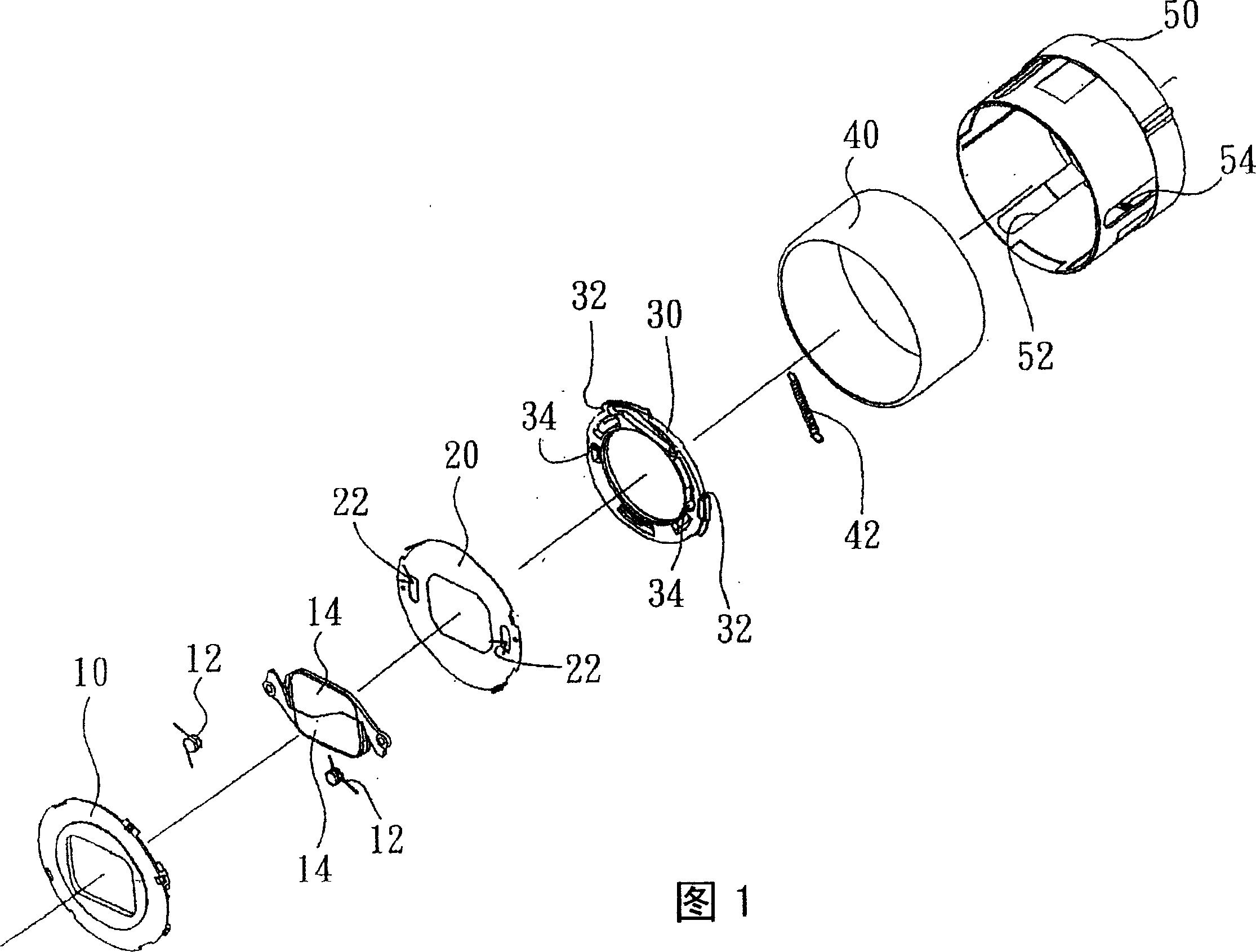
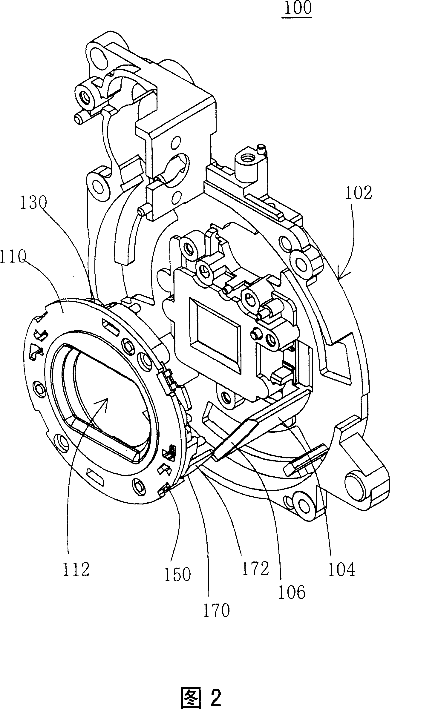
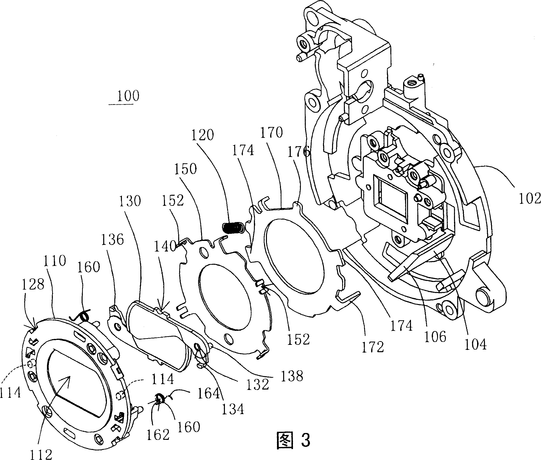
[0041] As shown in Fig. 2 and Fig. 3, it is a three-dimensional and exploded view of the present invention. The lens protection cover module 100 of the present invention includes: a front substrate 110 , a fixing plate 150 , at least one protection cover 130 , a driving plate 170 and an interference component 104 . The front substrate 110 has a mirror hole 112 . A lens group (not shown) disposed between the protective cover 130 and the lens base 102 captures an external light source through the mirror hole 112 to form an image. The fixing plate 150 is connected to a first elastic component 120 . In addition, the fixing plate 150 and the front base plate 110 are fixed relative to the protective cover 130 ; the fixed here means that there is no relative rotation between the two after the assembly is completed. The protective cover 130 has a pivot 114 and a lever 138 . The pivot 114 is located between the front base 110 and the fixing plate 150 so that the protective cover 130 ...


PUM


Abstract

The present invention relates to a protector module of lens can be used together with a camera, and comprises a front substrate, a fixing plate, at least one protector, a driving plate and a lens base, wherein, the front substrate has a lens hole, and the fixing plate is provided with a first elastic component; moreover , the fixing plate and the front substrate are relatively fixed; the protector has a pivot shaft and a push-rod, wherein, the pivot shaft is arranged between the front substrate and the fixing plate; the protector can rotate corresponding to the pivot shaft to position at a first position for covering the lens hole and at a second position for opening the lens hole; the driving plate is provided with a leaning surface and a pushing component; one side of the driving plate is buckled with the first elastic component; the pushing component can move the push-rod; moreover, the driving plate can rotate correspond to the fixing plate; the lens base is provided with an interfering component and a second leaning surface opposite to the first leaning surface; moreover, the driving plate can move in parallel along axial direction corresponding to the interfering component.

Description

technical field [0001] The present invention relates to a camera module, and in particular to a lens protection cover module. Background technique [0002] With the advancement of technology, the design of digital camera lens is becoming more and more complicated and precise. However, in a relatively small space, it is a huge challenge and mission for developers to design a relatively known digital camera that has the same function or even surpasses the known function. [0003] As for the variable-focus multi-tube lens, as shown in FIG. 1 , it is an exploded view of a known drive lens dust cover module. A known lens dust cover includes a base plate 10 , a set of first springs 12 , a dust cover 14 , a fixed plate 20 , a driving plate 30 , a second spring 42 , a rotating barrel 40 and a diameter barrel 50 . The rotating cylinder 40 is sleeved on the diameter cylinder 50 , and the base plate 10 , the dust cover 14 , the fixing plate 20 and the driving plate 30 are respectivel...

Claims


Application Information

Patent Timeline
IPC IPC(8): G03B17/02
Inventor 郭明道
Owner BENQ CORP
Why Eureka
Try Eureka