
Output circuit of calculation amplifier

An output stage circuit, operational amplifier technology, applied in differential amplifiers, DC coupled DC amplifiers, etc., can solve the problems of lower output stage output efficiency, complex circuit structure, and high input impedance, to increase the maximum output current and simplify the circuit. , Improve the effect of boasting

Active Publication Date: 2008-03-19
RDA TECH
View PDF0 Cites 4 Cited by
  • Summary
  • Abstract
  • Description
  • Claims
  • Application Information

AI Technical Summary

Problems solved by technology

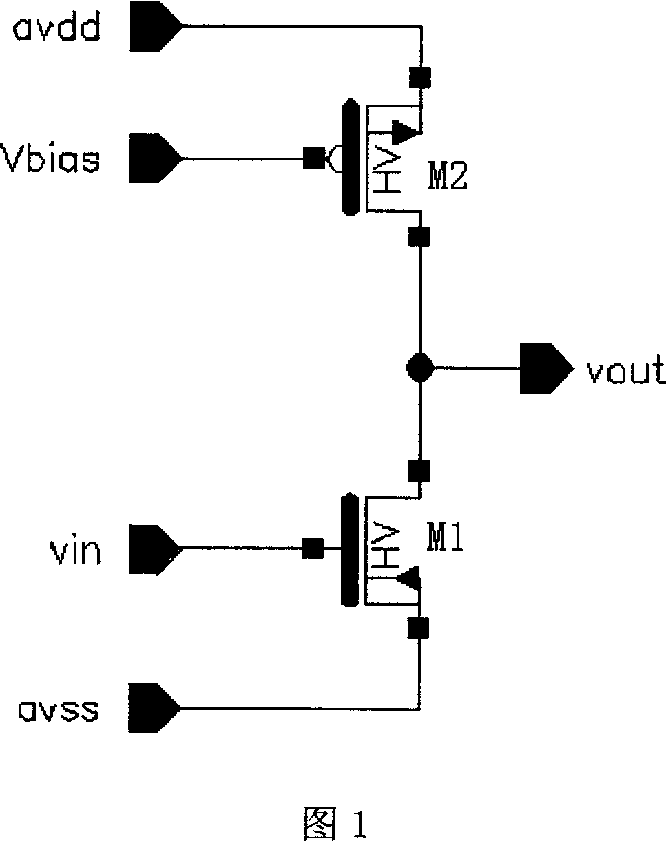
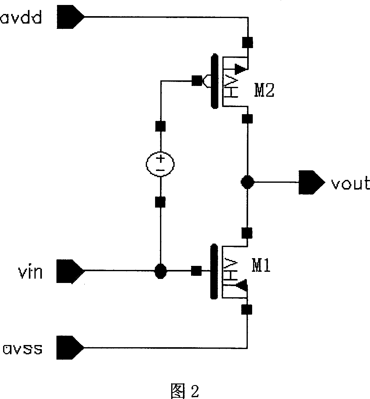
[0007] The class AB output stage requires a constant voltage source circuit. In order to avoid affecting the gain of the previous stage, its input impedance must be relatively high, which is more complicated to implement. After adding a constant voltage source circuit, the output efficiency of the entire output stage is also greatly reduced. , and the circuit structure is more complex

Method used


Image

  • Output circuit of calculation amplifier
  • Output circuit of calculation amplifier
  • Output circuit of calculation amplifier

Examples


Embodiment Construction

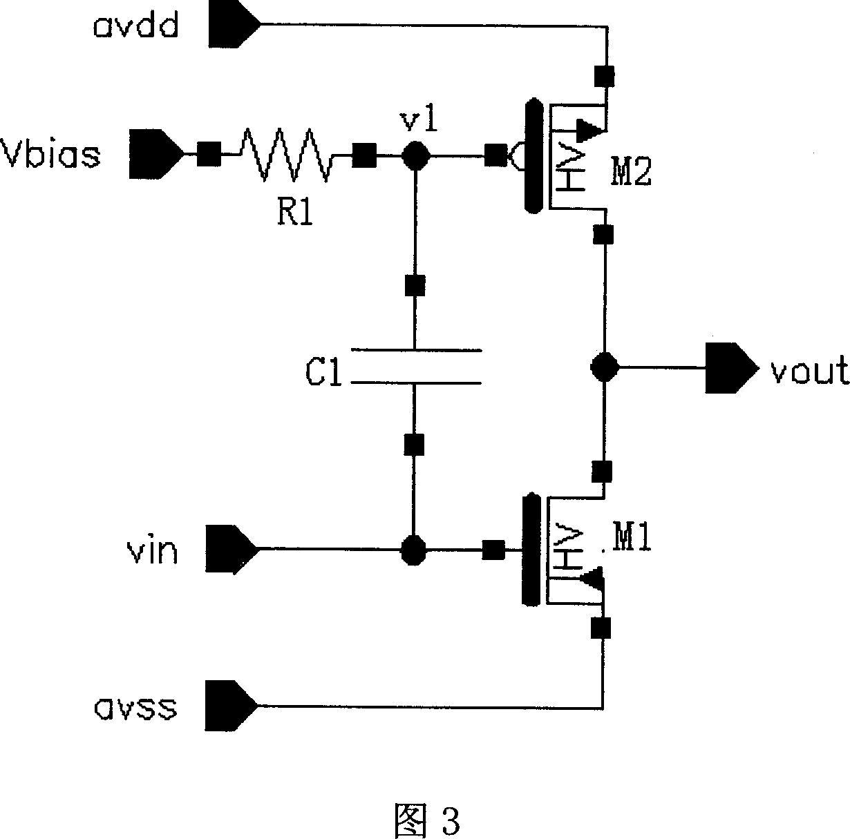
[0015] The output stage circuit of the operational amplifier of the present invention can be seen in FIG. 3, which includes two transistors M1 and M2 whose drains are connected together. The drains of the transistors M1 and M2 are used as output terminals, and the source of the transistor M2 is connected to At the power supply terminal, the source of the transistor M1 is grounded, the gate of the transistor M1 is used as an input terminal, the gate of the transistor M2 is connected with a resistor R1, and the resistor R1 is not connected to the end of the transistor M2 as a voltage bias Set the input terminal, and a capacitor C1 is connected between the transistors M1 and M2.

[0016] The transistor M1 is an NMOS transistor, the transistor M2 is a PMOS transistor, the input terminal vin is connected to the gate of the transistor M1, the source of the transistor M1 is grounded avss, and the drain of the transistor M1 is connected with the drain of the M2 to form the output stage. T...


PUM


Abstract

The invention discloses an output stage circuit of an operational amplifier, which comprises two triodes M1 and M2 with the drain electrodes thereof connected together, wherein the drain electrodes of the triodes M1 and M2 are used as an output terminal, the source electrode of the triode M2 is connected with a power end, the source electrode of the triode M1 is grounded, the grid electrode of the triode M1 is used an input terminal, the grid electrode of the triode M2 is connected with a resistor R1, the resistor R1 is not connected with one end of the triode M2 and used as a voltage biasing input terminal, and a capacitor C1 is connected between the triodes M1 and M2. The invention adds a capacitor between the grid electrodes of the two triodes, so as to omit a constant voltage source circuit, remarkably simply the circuit, as well as to improve the conduction of the circuit, increase the maximum output circuit, and improve the output efficiency of the output stage.

Description

Technical field [0001] The invention relates to an analog circuit, in particular to an output stage circuit of an operational amplifier. Background technique [0002] Operational amplifier is a key component of analog circuit design. It is widely used in the design of filters, digital-to-analog converters, and analog-to-digital converters. [0003] The operational amplifier consists of an internal gain stage and an output stage. The output stage is mainly designed to drive the load. In order to obtain a larger output voltage swing on a small load resistance, the output stage is required to output a large current. A large load capacitor also requires a large output current to provide the required charge and discharge current to meet the requirements of transient response. [0004] Nowadays, the methods to realize the output stage of operational amplifiers include Class A amplifiers and Class AB push-pull amplifiers. [0005] The structure of the Class A amplifier output stage is s...

Claims


Application Information

Patent Timeline
Patent Type & Authority Applications(China)
IPC IPC(8): H03F3/45
Inventor 魏述然周震
Owner RDA TECH
Learn More