A high-efficiency energy-saving current amplifier

A current amplifier, high-efficiency and energy-saving technology, applied in the direction of power amplifiers, can solve the problems of large power loss, low precision, and small maximum output current, and achieve the effects of reducing power loss, improving sampling accuracy, and increasing the maximum output current

Inactive Publication Date: 2018-01-16
NORTH CHINA ELECTRIC POWER UNIV (BAODING)
View PDF4 Cites 0 Cited by
  • Summary
  • Abstract
  • Description
  • Claims
  • Application Information

AI Technical Summary

Problems solved by technology

[0003] The invention provides a high-efficiency energy-saving current amplifier, which can solve the problems of low sampling accuracy, large power loss and small maximum output current of the traditional current amplifier

Method used


Image

  • A high-efficiency energy-saving current amplifier
  • A high-efficiency energy-saving current amplifier

Examples


Embodiment Construction

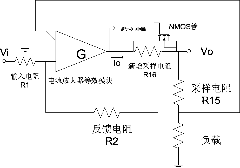
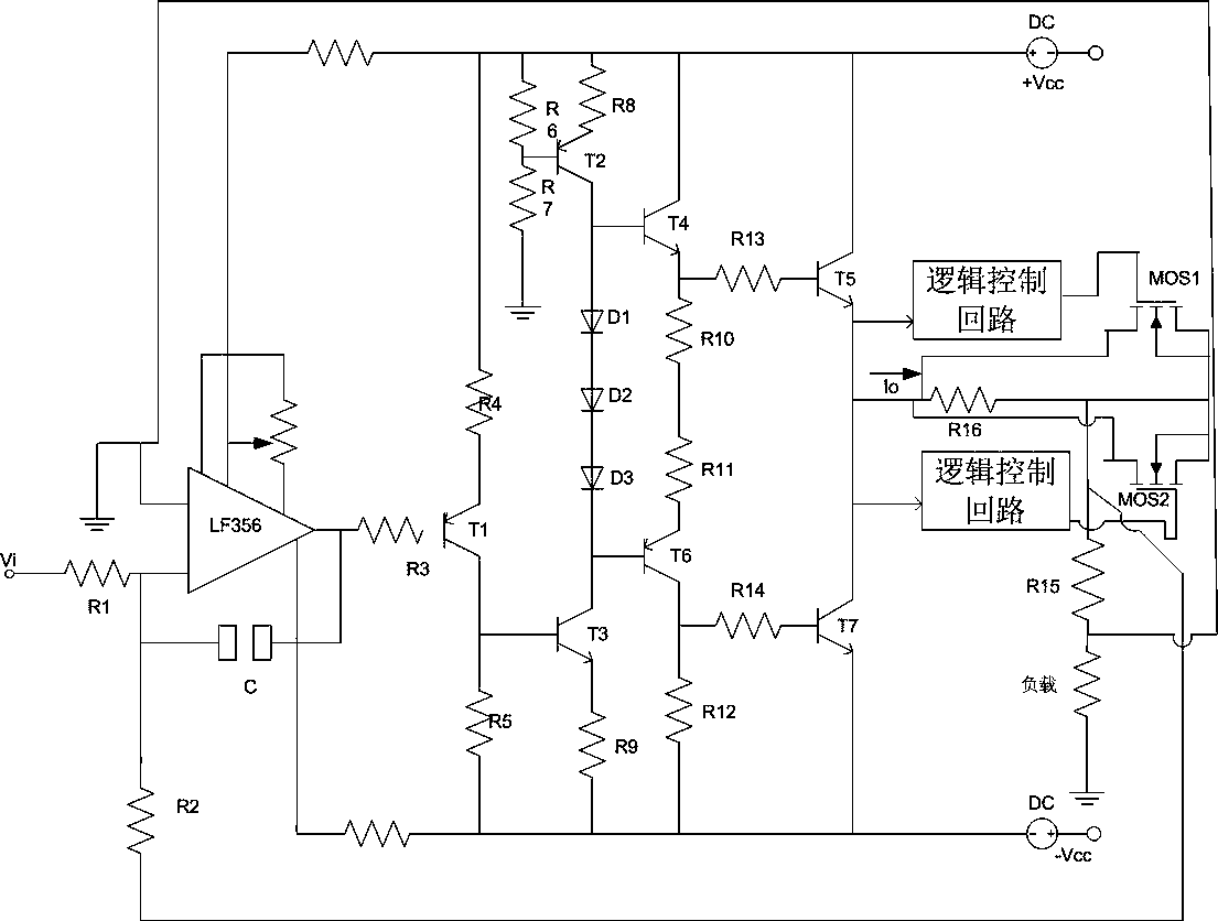
[0016] The present invention provides a high-efficiency energy-saving current amplifier. The present invention will be further described below in conjunction with the description of the drawings and specific implementation methods.

[0017] refer to figure 1 , figure 2 As shown, the high-efficiency and energy-saving current amplifier is used in the relay protection tester, and is composed of an input stage, a driving stage, and an output stage. The input stage is composed of LF356 operational amplifier, the driving stage is composed of transistors T1 and T3, and the output stage is composed of complementary Darlington circuit. When the collector of T3 is in the positive half cycle, the transistors T4 and T5 are turned on. When the collector of T3 is in the negative half cycle, the transistors T6 and T7 are turned on. The transistor T3 drives the transistors T4 and T6, and then the transistors T4 and T6 drive the transistors T5 and T7 respectively.

[0018] When the curren...


PUM


Abstract

The invention relates to a high-efficiency energy-saving current amplifier, which belongs to the field of relay protection test equipment, and in particular relates to a relay protection tester device. The drain D of the NMOS tube is connected to the output terminal of the equivalent module of the current amplifier as the input terminal, the source of the NMOS tube is connected to the load as the output terminal, and the gate is connected to the logic control circuit; the value of the sampling resistor R15 is reduced from 0.1 ohm to 0.02 ohm ; Add a new sampling resistor R16 with a value of 0.3 ohms between the drain D and the source S; control the NMOS tube to be turned off by the gate voltage, when the output current of the current amplifier is greater than or equal to 15 amperes, the gate voltage reaches the threshold value, The NMOS tube is in the closed state, and the current flows through the NMOS tube branch; when the output current of the current amplifier is less than 15 amperes, the gate voltage does not reach the threshold, the NMOS tube is in the disconnected state, and the current flows through the newly added sampling resistor branch. The present invention utilizes the ability of the gate voltage of the NMOS tube to reach the threshold to form a conductive channel between the source and the drain, realizes the current amplifier of the relay protection tester to reduce power loss, improve sampling accuracy, reduce investment, and increase the maximum output current Etc.

Description

technical field [0001] The invention belongs to the field of relay protection test equipment, in particular to a relay protection tester device. Background technique [0002] In the field of relay protection testing, relay protection testers are the most common measuring instruments. It is based on the "Technical Conditions of Microcomputer Relay Protection Test Device (Discussion Draft)" issued by the Ministry of Electric Power, extensively listens to user opinions, summarizes the advantages and disadvantages of similar domestic products, and makes full use of modern advanced microelectronic technology and devices Realized a relay protection testing instrument. The analog voltage output from the relay protection tester must be amplified by the amplifier before it can be sent to the input terminal of the relay under test. The power amplifier is further divided into a voltage amplifier and a current amplifier. As an important part of the experimental device, the performance...

Claims


Application Information

Patent Timeline
Patent Type & Authority Patents(China)
IPC IPC(8): H03F3/20
Inventor 夏瑞华白坚实刘博
Owner NORTH CHINA ELECTRIC POWER UNIV (BAODING)
Why Eureka
Try Eureka