
A standing wave ration detection device and method for time division duplex communication system

A standing wave ratio detection and communication system technology, applied in the direction of measurement devices, transmission systems, wireless communications, etc., can solve problems such as VSWR calculation errors, inability to effectively avoid errors, and system complexity

Inactive Publication Date: 2008-03-19
RUGAO CHANGJIANG SCI & TECHCAL IND CO LTD
View PDF1 Cites 69 Cited by
  • Summary
  • Abstract
  • Description
  • Claims
  • Application Information

AI Technical Summary

Problems solved by technology

Lead to the subsequent decline in the standing wave ratio detection accuracy
Again, this method selects the front and reverse power detection through the radio frequency switch, so that the forward power detection and the reverse power detection are not signals at the same time. This method will bring errors in the measurement results
In this method, only the average of multiple measurements is used to improve, but it cannot effectively avoid the error of the measurement result
Again, in order to solve the shortcoming that the forward power detection and reverse power detection are not signals at the same time, the method adopts a long-term averaging method, which increases the computational complexity and makes the system complex
Again, this method uses complex dB representation, and the intermediate conversion process brings VSWR calculation error

Method used


Image

  • A standing wave ration detection device and method for time division duplex communication system
  • A standing wave ration detection device and method for time division duplex communication system
  • A standing wave ration detection device and method for time division duplex communication system

Examples


Embodiment Construction

[0136] Preferred embodiments of the present invention will be specifically described below with reference to the accompanying drawings, wherein the accompanying drawings constitute a part of the application and are used together with the embodiments of the present invention to explain the principle of the present invention.

[0137] In order to facilitate understanding, the following will take TD-SCDMA system, a typical time division duplex communication system in the third generation mobile communication, as an example to illustrate the principle of the present invention.

[0138] The invention proposes a standing wave ratio detection method and device.

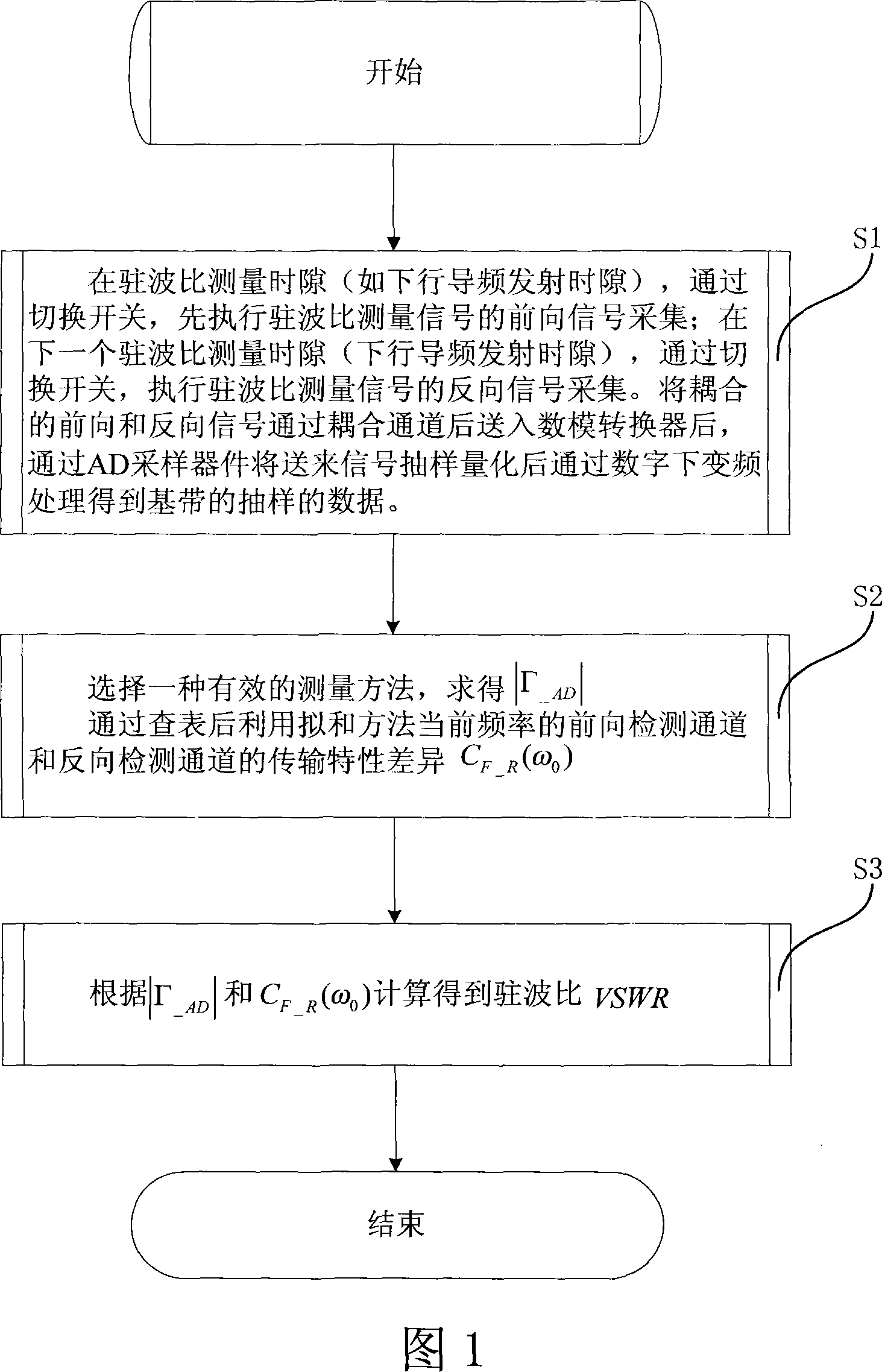
[0139] Fig. 1 shows the standing wave ratio detection method according to the present invention, and it comprises the following steps:

[0140] Step S1, in the standing wave ratio measurement time slot (such as the downlink pilot transmission time slot), by switching the switch (the switch control sequence during the standin...


PUM


Abstract

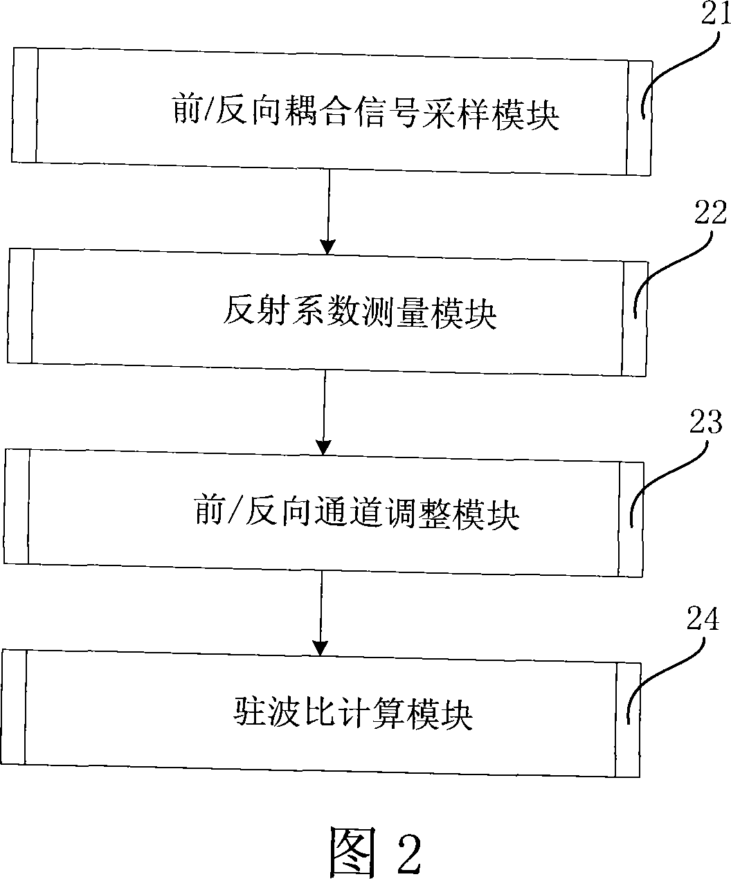
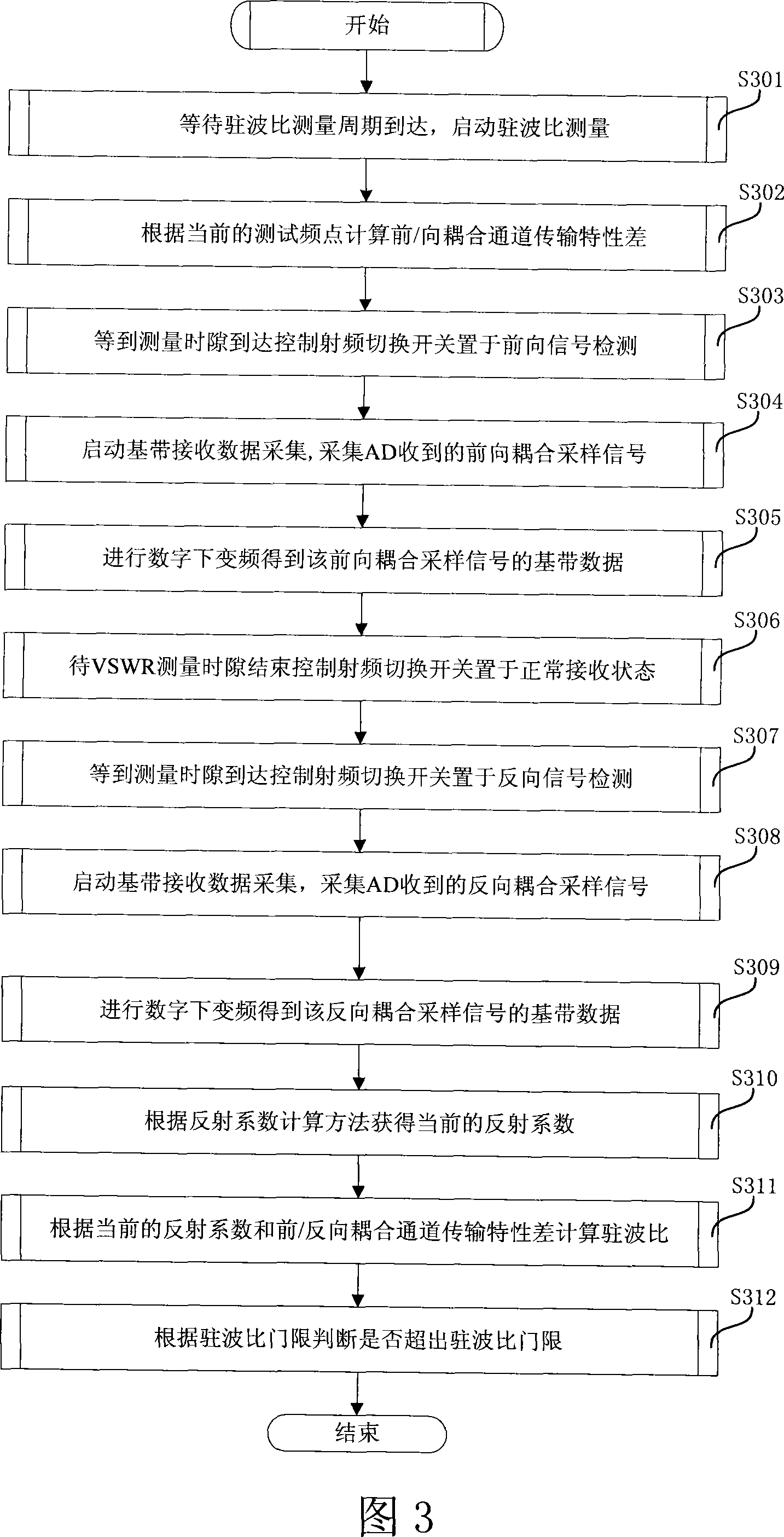
The invention relates to a detection method of standing-wave ratio of a time division duplex communication system, which comprises the following steps: a forward signal is sampled by switching a switch at a time interval of standing-wave ratio measurement; a reverse signal is sampled by switching the switch at the next time interval of standing-wave ratio measurement; the forward and the reverse signals is coupled and delivered to a digital-to-analog converter through a coupling passage, the delivered signal is sampled and quantized by using an AD sampler and processed by means of digital down-conversion to obtain a sampled data of baseband; a reflection coefficient |gamma_AD| is obtained by calculating, the transmission characteristic difference CF_R(Omega 0) between a forward detection channel and a reverse detection channel is obtained at the current frequency after table lookup process; and the standing-wave ratio VSWR is calculated based on the reflection coefficient |gamma_AD| and the transmission characteristic difference CF_R(Omega 0). Therefore, the invention realizes the multiplexing of a normal reception channel and the reverse and the forward standing-wave ratio channels, enables the normal reception channel to be used in standing-wave ratio detection, and ensures the equivalency of front / reverse power samplings by measuring the front and the reverse powers of the pilot frequency.

Description

technical field [0001] The invention relates to a time-division duplex mobile communication system in the technical field of mobile communication, in particular to a method and device for detecting standing wave ratio of a time-division duplex mobile communication system. Background technique [0002] Base station VSWR (Voltage Standing Wave Ratio, standing wave ratio) is an important parameter of radio frequency. The standing wave is caused by the impedance mismatch in the transmission path. When there is an impedance mismatch in the transmission path, a part of the signal power will be reflected back, and the reflected signal is superimposed with the transmitted signal to form a standing wave. A relatively large standing wave means that the signal reflection is relatively strong, which means that the matching effect on the transmission path is relatively poor. In a transmitting system, if the standing wave is relatively large (usually caused by poor physical connection du...

Claims


Application Information

Patent Timeline
Patent Type & Authority Applications(China)
IPC IPC(8): H04Q7/34H04B17/00G01R27/06H04B1/707H04L25/03H04W24/02
Inventor 王斌刘丽莉赵羽
Owner RUGAO CHANGJIANG SCI & TECHCAL IND CO LTD
Learn More