Track system and concrete slab of a fixed track

A technology for concrete slabs and fixed tracks, applied in the field of track systems, can solve the problems that railway transportation cannot be interrupted, reconstruction measures cannot be taken, difficulties, etc.

Inactive Publication Date: 2008-03-19
MAX BOGL BAUUNTERNEHMUNG
View PDF0 Cites 0 Cited by
  • Summary
  • Abstract
  • Description
  • Claims
  • Application Information

AI Technical Summary

Problems solved by technology

[0004] From an engineering standpoint, there is not much difficulty in building a new fixed track, however, if a track system has to be rebuilt from the ballast bed to the fixed track, it becomes difficult because most time rail transport cannot be interrupted and thus extensive reconstruction measures cannot be taken

Method used


Image

  • Track system and concrete slab of a fixed track
  • Track system and concrete slab of a fixed track
  • Track system and concrete slab of a fixed track

Examples


Embodiment Construction

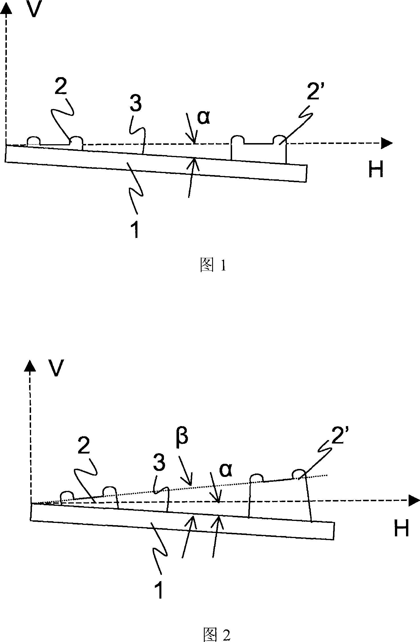
[0026] Figure 1 is a diagram of a horizontal rail arrangement, where the dotted arrow lines H and V indicate the horizontal and vertical directions, rail seats 2 and 2' have been placed on the concrete slab 1, the rail seats 2 and 2' along the horizontal line H so that the rails which are subsequently assembled on the rail bases 2 and 2' are also arranged horizontally to each other. The concrete slab 1 has an upper surface 3 inclined with respect to the horizontal H at an angle α showing the inclination of the concrete slab 1 which allows rainwater to flow out of the concrete slab 1 towards the rail seat 2'. Although the slope of the two rail supports 2 and 2' arranged parallel to one another is horizontal, the upper surface 3 of the concrete slab 1 still allows rainwater to flow out to a defined outer side. Accordingly, the rail seat 2' is made higher than the rail seat 2 in relation to the upper surface 3.

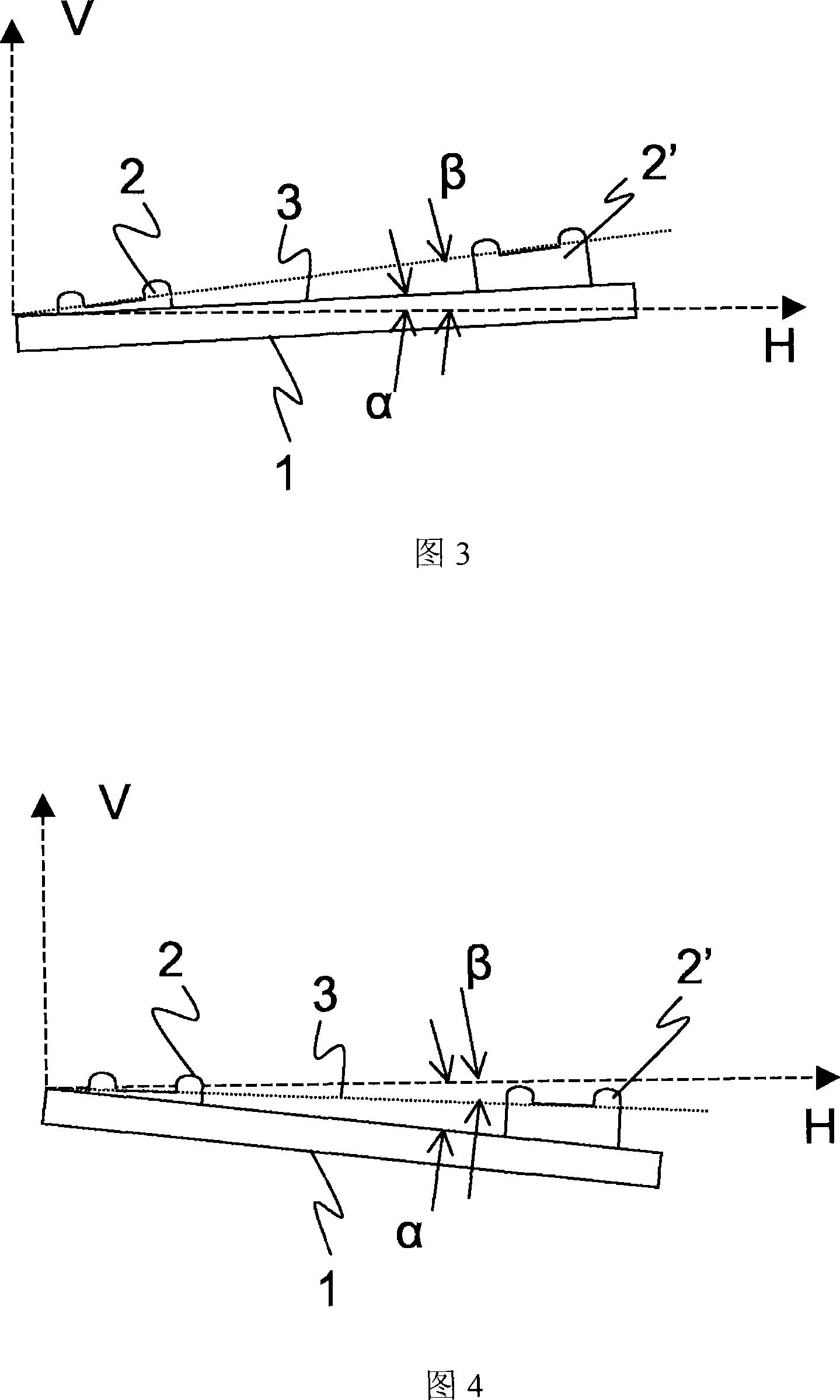
[0027] Figure 2 shows a representation of a concrete slab accordin...


PUM


Abstract

The invention relates to track system having two substantially parallel tracks (6) which are disposed on respective concrete slabs (1) of a fixed track. The slabs (1) comprises a plurality of track supports (2, 2′) for receiving and fastening thereon two parallel rails (5). The top surfaces (3) of the slabs (1) of the two tracks (6) are inclined independent of the a guiding system of the tracks (6) and of the corresponding position of the rail supports (2, 2′) relative to the two outer sides (8) of the track system and form a slope. The invention also relates to a concrete slab of a fixed track, which comprises supports (2, 2′) for the first rail (5) which are higher in relation to the top surface (3) of the slab (1) than the supports (2, 2′) for the second rail (5).

Description

technical field [0001] The present invention relates to a rail system having two substantially parallel rails, each of which is placed on a concrete slab, and the concrete slab has a plurality of rail seats for placing and fixing two mutually parallel rails thereon. Steel rails, the invention also relates to corresponding concrete slabs for fixing the rails. Background technique [0002] If the track is conventionally placed on a ballasted track bed, rainwater seeps out of the ballast of the track bed and is guided to the outside along the subgrade protective layer. Thus, rainwater is largely prevented from accumulating near the tracks. However, tracks placed on ballasted beds are not conducive to high-speed rail transportation, so fixed tracks are installed in most cases. In the case of fixed rails, a hydrodynamically bonded support layer is built directly on the subgrade protection layer, on which the fixed rails are then placed. The aforementioned fixed track is made o...

Claims


Application Information

Patent Timeline
Patent Type & Authority Applications(China)
IPC IPC(8): E01B1/00E01B3/40
CPCE01B3/40E01B1/008E01B1/002
Inventor 斯特凡·博格尔
Owner MAX BOGL BAUUNTERNEHMUNG
Why Eureka
Try Eureka