
Flat-bed machine sinker and feed distance clip

A sinker and spacer technology, applied in textiles and papermaking, weft knitting, knitting, etc., can solve the problems of poor movement and the effect of knitted fabric completion, and achieve the effect of preventing gaps and vibrations

Active Publication Date: 2008-03-26
SHIMA SEIKI MFG LTD
View PDF2 Cites 3 Cited by
  • Summary
  • Abstract
  • Description
  • Claims
  • Application Information

AI Technical Summary

Problems solved by technology

When the side of the yarn guide spacer 5 is in strong contact with the sinker plate 4, it sometimes becomes a resistance to the swing of the sinker plate 4, which makes the action of pressing the knitted fabric into the knitted fabric by the force of the spring worse, and affects the completion of the knitted fabric

Method used


Image

  • Flat-bed machine sinker and feed distance clip
  • Flat-bed machine sinker and feed distance clip
  • Flat-bed machine sinker and feed distance clip

Examples


Embodiment Construction

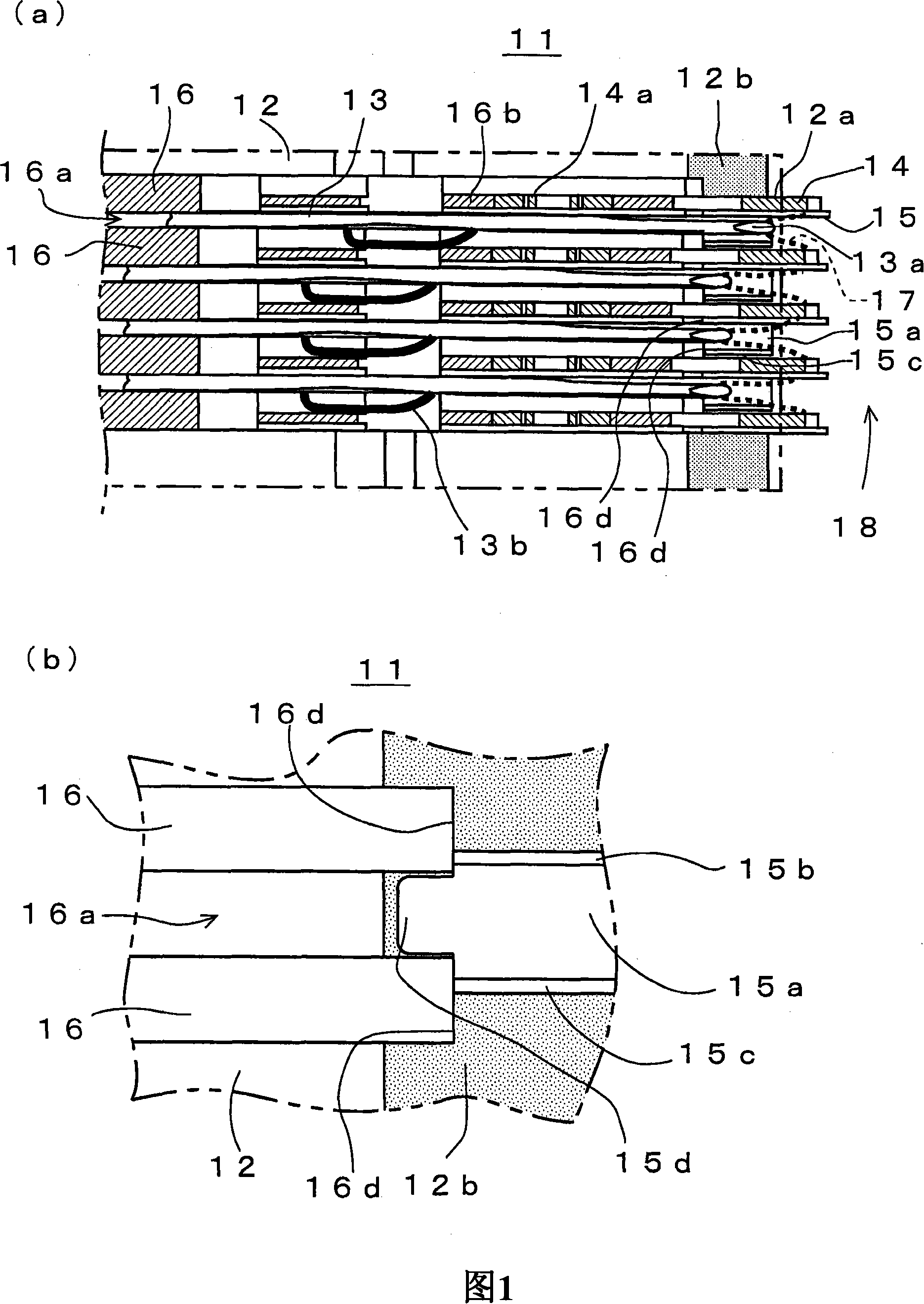
[0025] FIG. 1 shows the configuration of main parts of a sinker device 11 according to one embodiment of the present invention. (a) shows a partial planar structure near the front end of the needle bed 12, and (b) shows an enlarged part for preventing vibration. On the needle bed 12, needle plates 16 are arranged side by side at a pitch corresponding to the gauge of the flat knitting machine to accommodate the knitting needles 13, the sinker plate 14, and the yarn guide gauge 15. The needle bed 12 is provided with a groove for inserting the lower side of each needle plate 16 . The knitting needles 13 are housed in needle grooves 16a formed between the needle plates 16, and are slidably displaceable in the left and right directions of the drawing. As will be described later, the sinker plate 14 is integrally formed with a spring portion 14a that biases downward the side of the crest 18 that receives the yarn feed of the knitting yarn 17 and knits the knitted fabric. Near the ...


PUM


Abstract

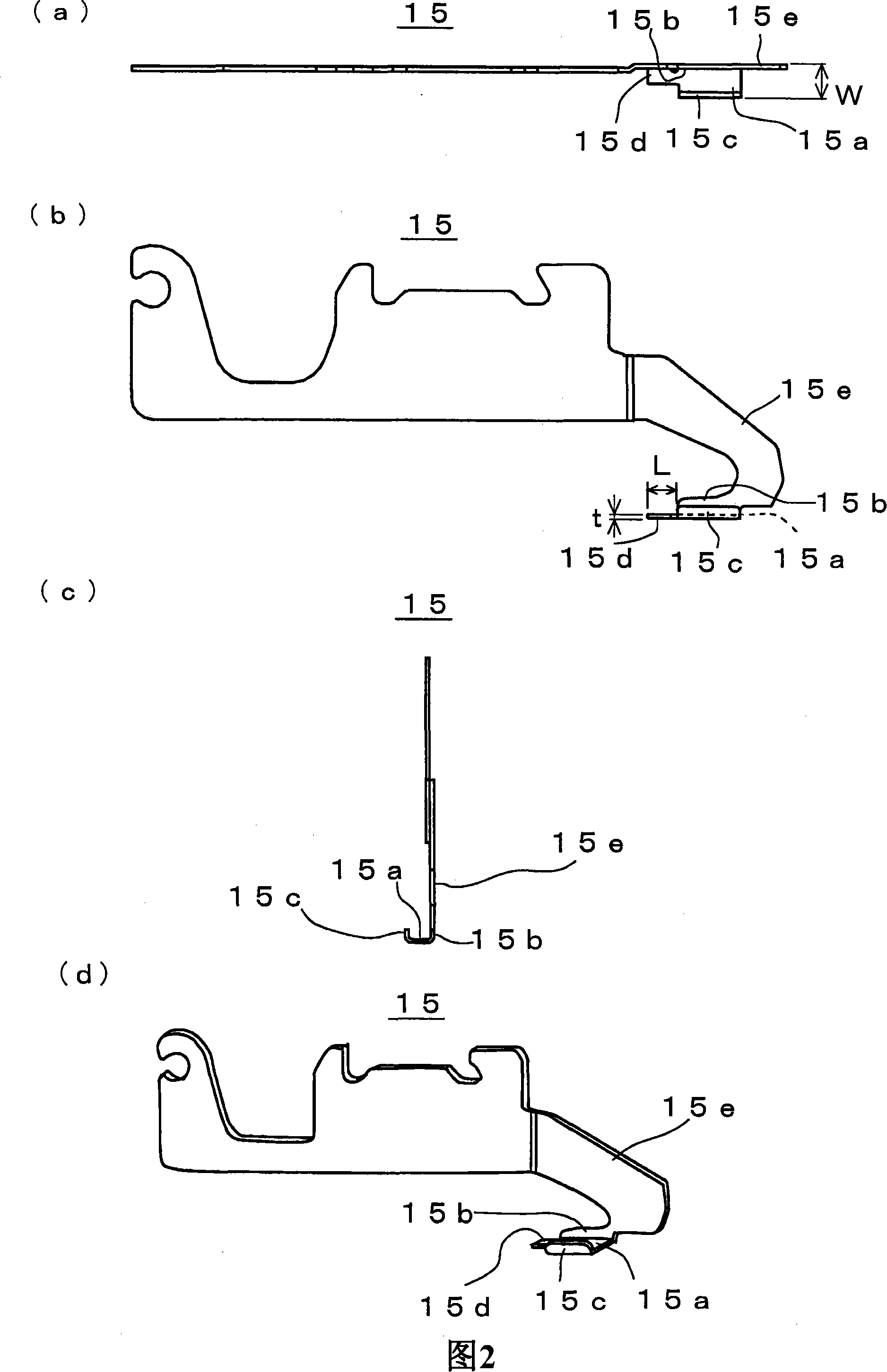
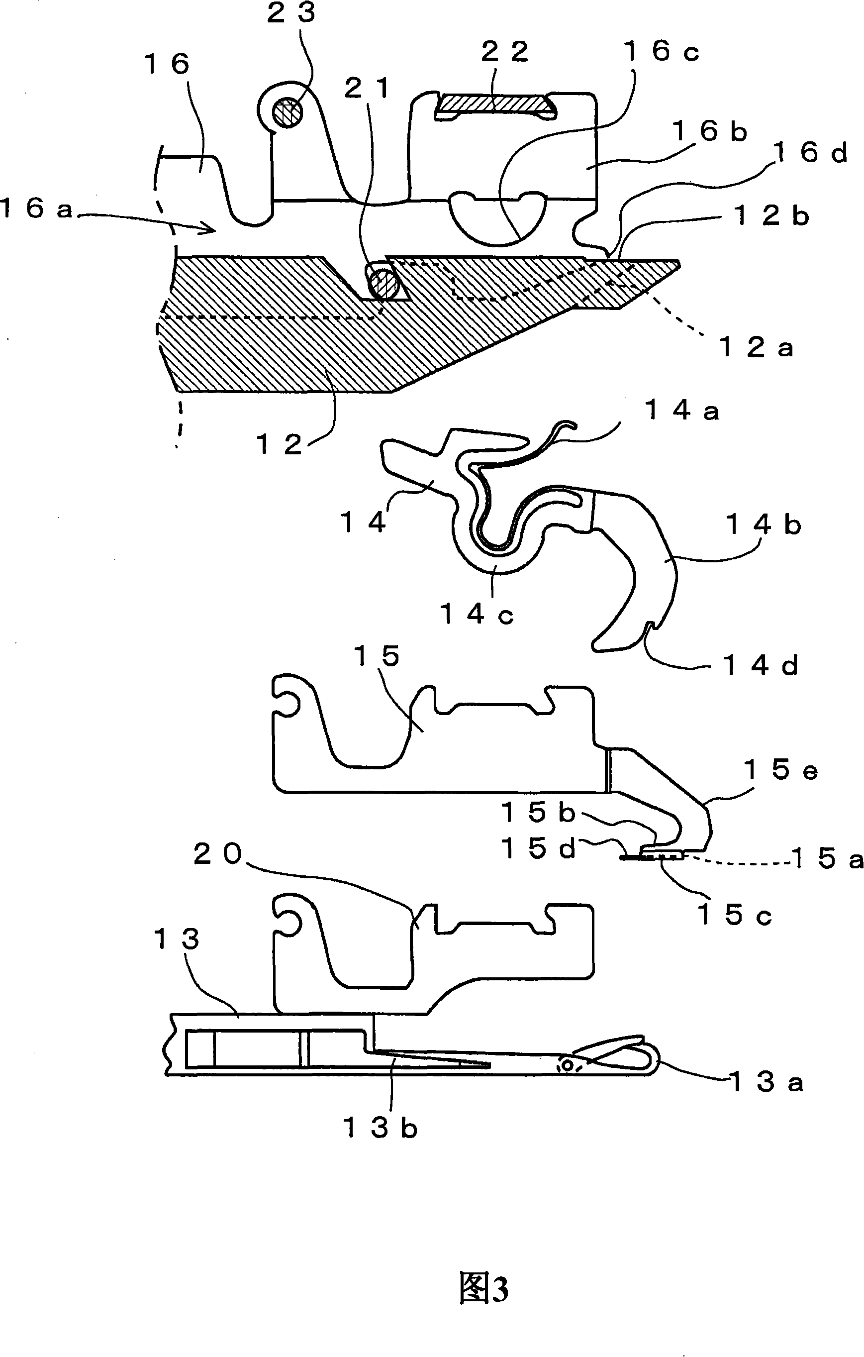
A horizontal machine sinker device capable of preventing the feed distance clip from vibrating and a feed distance clip are provided in the present invention. It has an extending part (15a), a knitting yarn fall-preventing parts (15b, 15c), and an entering part (15d) for preventing the feed distance clip from vibrating. The entering part (15d) enters from the middle of the extending part (15a) to a needle slot (16a) direction that is apart from gear open (18) direction, tow sides are clamped by a needle plate (16). On the upper surface of the needle bed (12), at the part arranged with the extending part (15a) and the entering part (15d), forming step part (12b). It can easily form step part (12b) by processing such as cutting needle bed (12) along the gear open (18) longitude direction. To lead the extending part (15a) to reliably prevent from vibration, when the entering part (15d) two sides end edges connects with the needle plate (16) end part (16d).

Description

technical field [0001] The invention relates to a sinker device and a yarn guide distance block of a flat knitting machine, which has a movable sinker plate that can swing forward and backward relative to the tooth mouth, and can prevent knitting yarn from being bitten into the sinker plate arranged on a needle bed. The guide groove. Background technique [0002] Conventionally, on a needle bed of a flat knitting machine, sinkers are arranged between a plurality of knitting needles arranged in parallel to advance and retreat toward the needle bed. The basic function of the sinker is to form a sinker arc together with the knitting needle when the knitting needle introduces the knitting yarn. When the stitches formed by the knitting arcs and the sinker arcs are stripped from the hooks of the knitting needles, they become old stitches and sag downwards in sequence to form a knitted fabric. When knitting a knitted fabric by sequentially forming stitches at the creases, the old...

Claims


Application Information

Patent Timeline
IPC IPC(8): D04B15/06D04B15/38
Inventor 森田敏明
Owner SHIMA SEIKI MFG LTD
Learn More