Optic switch

A technology of optical switches and optical fibers, applied in the field of optical switches, can solve problems such as poor alignment accuracy, achieve the effects of improving production efficiency, reducing alignment errors, and improving assembly yield

Inactive Publication Date: 2008-03-26
范光照
View PDF3 Cites 7 Cited by
  • Summary
  • Abstract
  • Description
  • Claims
  • Application Information

AI Technical Summary

Problems solved by technology

[0008] In order to solve the problem of poor alignment accuracy in the prior art, it is necessary to provide an optical switch that can reduce alignment errors

Method used


Image

  • Optic switch
  • Optic switch
  • Optic switch

Examples


Embodiment Construction

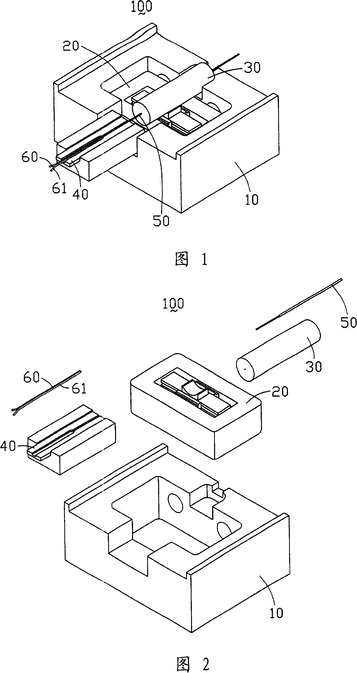
[0017] Please refer to FIG. 1 and FIG. 2 , which are a three-dimensional schematic diagram and a three-dimensional exploded schematic diagram of the optical switch of the present invention. The optical switch 100 includes a base 10; an optical path switching device 20, fixed on the base 10; an input optical fiber fixing sleeve 30, fixed on the optical path switching device 20; an output optical fiber fixing platform 40, fixed on the base One side of 10 is opposite to the optical path switching device 20; an input fiber 50 is fixed in the input fiber fixing sleeve 30; and the first and second output fibers 60, 61 are fixed on a rectangular shape of the output fiber fixing platform 40 groove.

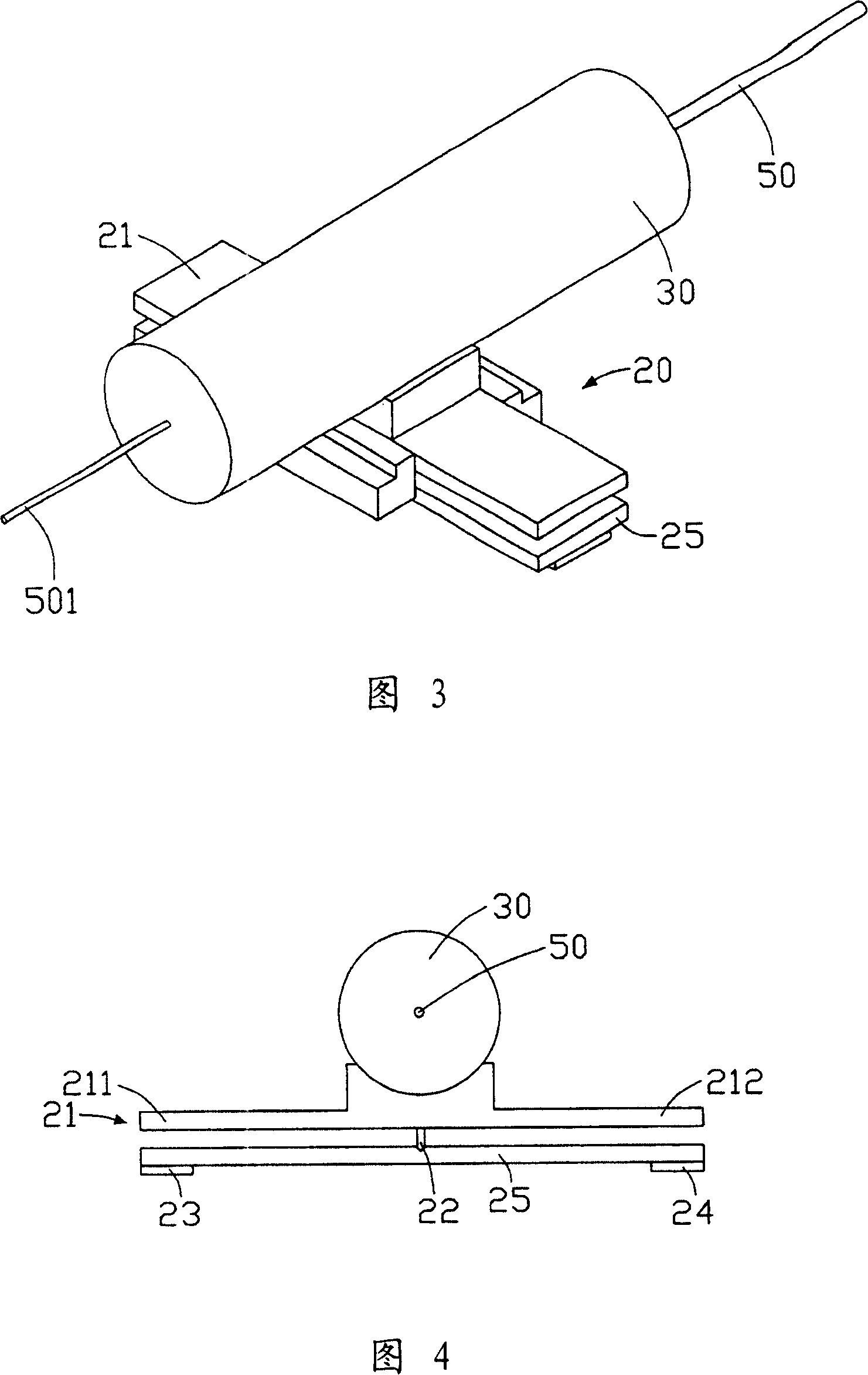
[0018] Please refer to FIG. 3 and FIG. 4 together, which are perspective schematic diagrams and cross-sectional schematic diagrams of the optical path switching device of the optical switch of the present invention. The optical path switching device 20 includes a rocker arm 21 and a rock...


PUM


Abstract

This invention relates to a kind of light switch, it includes a base, a fiber conversion setting, fixed in one end of the base, a output fiber fixed platform, fixed in the other end of the base, face to the fiber conversion setting, a input fiber fixed bushing take in a input fiber, fixed in the fiber conversion setting; and two output fiber, fixed partly in the flute of output fiber fixed platform. The end of the input fiber protrudes the input fiber fixed bushing and reaches the flute to contrapose with the output fiber end. Comparing with exist technology, because the light switch in this invention has fiber contraposition character that beeline to beeline and fiber to fiber. The end of input fiber and the output fiber are in beeline to beeline contraposition, it can reduce the contraposition error; and the end of input fiber and the output fiber of the light switch are open, it is convenient to span optical test instrument to observe the contraposition situation of the fiber end.

Description

technical field [0001] The invention relates to an optical switch, in particular to a line-to-line and fiber-to-fiber optical fiber-to-bit mechanical optical switch. Background technique [0002] Optical switch is one of the important components in optical communication, which can transmit optical signals directly, interleaved or multi-party in optical fiber network system. In the past, the widely used optical switch first converted the input optical signal into an electrical signal, then switched the electrical signal path, and then converted the electrical signal into an optical signal for a specific optical fiber output. This method is not only complicated but also consumes energy. It is not conducive to the popularization of optical fiber network in the future. [0003] With the continuous expansion of the application field of optical fiber, in order to obtain the desired optical signal transmission path in the optical transmission system, the conversion of optical sign...

Claims


Application Information

Patent Timeline
Patent Type & Authority Applications(China)
IPC IPC(8): G02B6/35
Inventor 范光照钟添东杨燿州林武郎
Owner 范光照
Why Eureka
Try Eureka