Method and device for generating impulse bandwidth modulation signals and its application

A pulse width modulation and signal technology, applied in the direction of output power conversion devices, electrical components, etc., can solve problems such as complex circuits, waste of integrated circuit pins, poor design or modification of PWM circuits, etc.

Active Publication Date: 2008-03-26
RICHTEK TECH
View PDF3 Cites 28 Cited by
  • Summary
  • Abstract
  • Description
  • Claims
  • Application Information

AI Technical Summary

Problems solved by technology

In U.S. Patent No. 6522115, a non-linear ramp signal is used, but this method needs to detect the inductor current, so one more pin for detecting the current is needed, resulting in a waste of integrated circuit (IC) pins, and the PWM circuit is relatively bad design or modification
In U.S. Patent No. 6593725, a pulse signal generator is used to control the ramp signal and the pulse width modulation signal, but the input voltage of the power converter must be sensed, and the circuit becomes too complicated

Method used


Image

  • Method and device for generating impulse bandwidth modulation signals and its application
  • Method and device for generating impulse bandwidth modulation signals and its application
  • Method and device for generating impulse bandwidth modulation signals and its application

Examples


Embodiment Construction

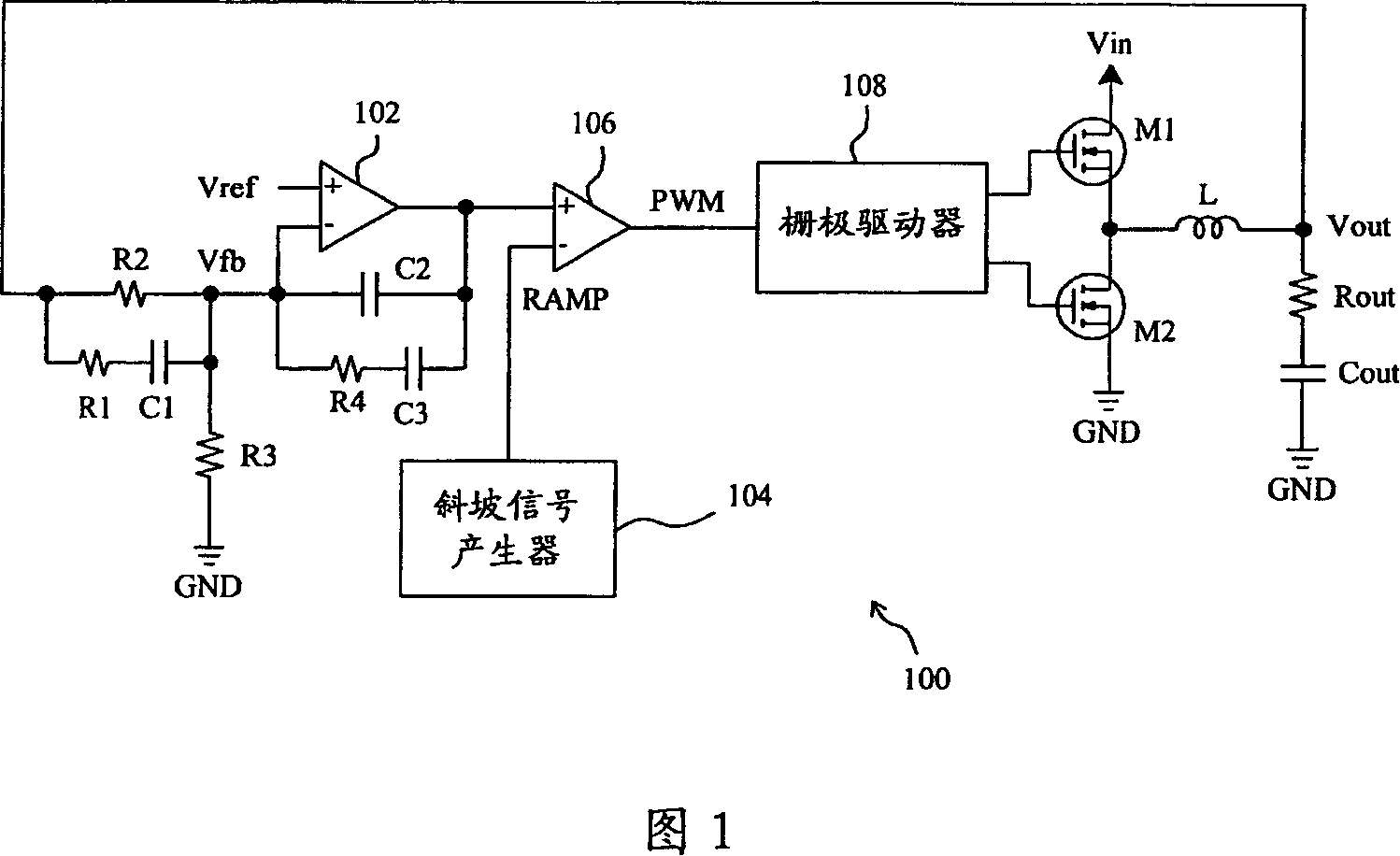
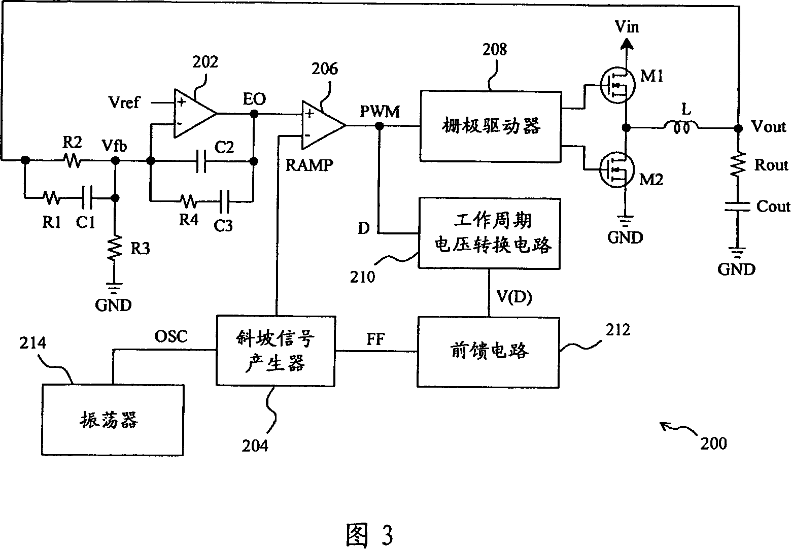
[0041] In an embodiment of the present invention, as shown in FIG. 3, the PWM power converter 200 is similar to the known PWM power converter 100 in FIG. The magnitude of D is converted into a linearly related voltage V(D), a feedforward circuit 212 converts the voltage V(D) into a feedforward signal FF, and a ramp signal generator 204 oscillates according to an oscillator 214 The signal OSC and the feedforward signal FF generate an oscillating linear ramp signal RAMP to the pulse width modulator 206 . In this embodiment, the slope of the oscillating linear ramp signal RAMP is modulated by the feedforward signal FF, that is, the duty cycle D, so the slope of the oscillating linear ramp signal RAMP changes as the duty cycle D changes.

[0042] Since the duty cycle D is obtained directly from the PWM signal to modulate the slope of the oscillating linear ramp signal RAMP, the instantaneous response of the PWM power converter 200 is improved. And because the slope of the oscilla...


PUM


Abstract

This invention relates to a method and a device for generating pulse width modulation signals, a supply converting method and a supply converter using the method and the device including comparing an error signal with an oscillation linear slope signal to generate a pulse width modulation signal, in which, said signal provides a piece of information of a working period to modulate the slope of the oscillation slope signal or the quasi-position of the error signal to further modulate the period of the work so as to improve stability of instant response of the supply converter and pulse width modulation loop.

Description

technical field [0001] The present invention relates to a power conversion method and a power converter, in particular to a pulse width modulation (Pulse Width Modulation; PWM) signal generation method and device applied to the power conversion method and power converter. Background technique [0002] As shown in FIG. 1, in a typical PWM power converter 100, the error amplifier 102 compares a feedback voltage Vfb derived from the output terminal Vout with a reference voltage Vref to generate an error signal EO, and the pulse width modulator 106 converts the error The signal EO is compared with the oscillating linear ramp signal RAMP with a fixed slope generated by a ramp signal generator 104 to generate a PWM signal, which switches the transistors M1 and M2 through the gate driver 108. The PWM signal has a duty cycle (duty) to determine the transistor The turn-on (on) and turn-off (off) times of M1 and M2 thus regulate the output voltage Vout. The ratio of the input voltage...

Claims


Application Information

Patent Timeline
IPC IPC(8): H02M1/00
Inventor 张财福戴良彬
Owner RICHTEK TECH
Why Eureka
Try Eureka