Optical system with diffraction optical element used for mapping signal light onto a detector

A technology of diffractive optical elements and optical systems, applied in the directions of optical elements, optics, fluorescence/phosphorescence, etc.

Inactive Publication Date: 2008-03-26
KONINKLIJKE PHILIPS ELECTRONICS NV
View PDF1 Cites 5 Cited by
  • Summary
  • Abstract
  • Description
  • Claims
  • Application Information

AI Technical Summary

Problems solved by technology

However, the problem with this approach is that the signal light leaving the glass substrate is distributed over a large angular range that the detector must cover in order to collect all the available signal light
Furthermore, signal light from different light sources mixes, so the light cannot be spatially separated by detectors

Method used


Image

  • Optical system with diffraction optical element used for mapping signal light onto a detector
  • Optical system with diffraction optical element used for mapping signal light onto a detector

Examples


Embodiment Construction

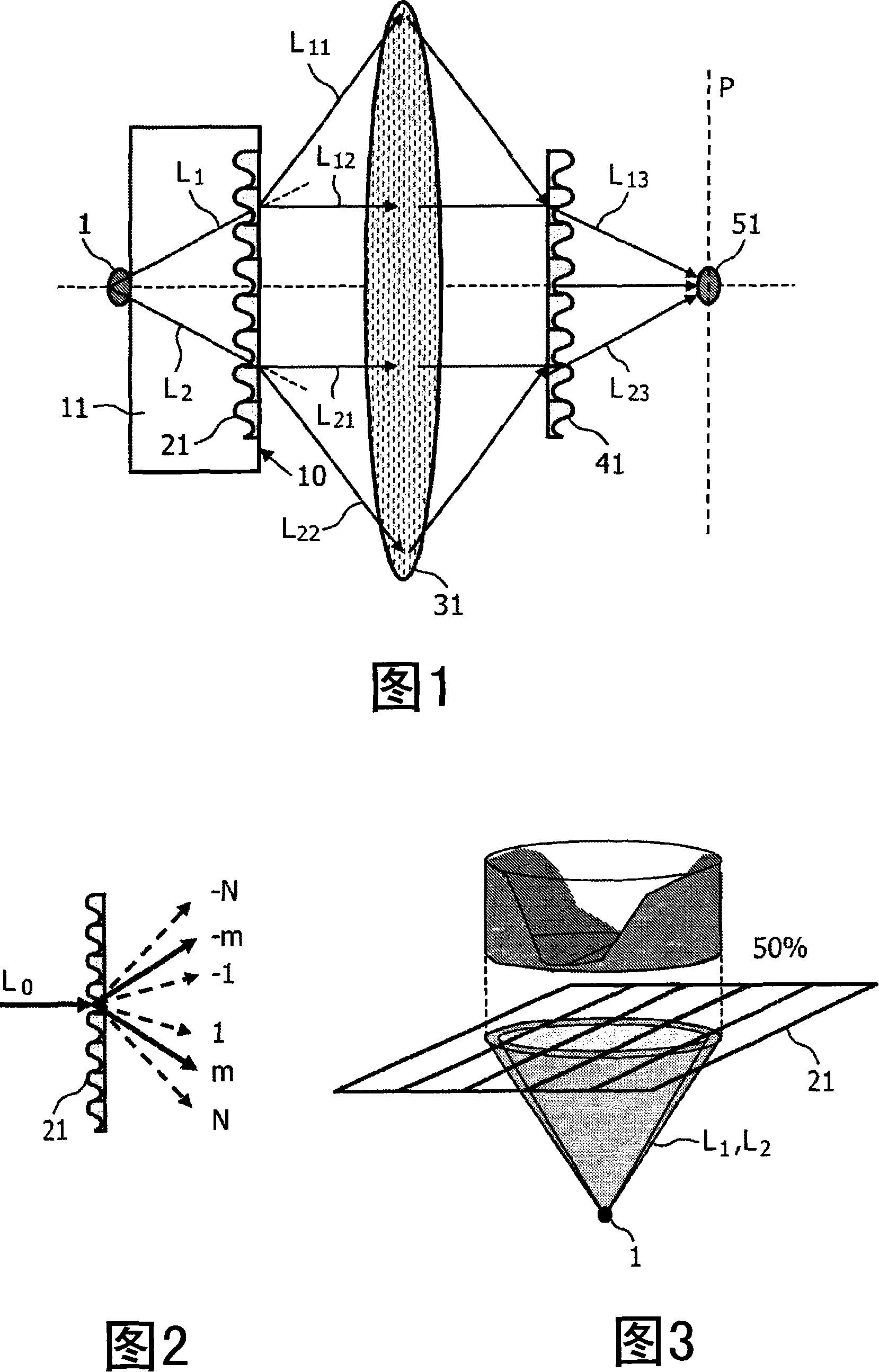
[0033] Fig. 1 schematically shows the setup of an optical system according to a preferred embodiment of the present invention. The light source 1 is arranged adjacent to a transparent substrate 11, which may be, for example, a flat glass plate. The light source 1 may be a point of the sample material to be investigated that emits signal light (eg fluorescence). However, it should be noted that such a research system is only one example of the application of the present invention.

[0034] A detailed analysis of the propagation of the signal light emitted by the luminescent particle 1 through the glass substrate 11 can be found in WO02 / 059583A1, which is hereby incorporated into this application by reference. According to this analysis, a considerable portion of the signal light emitted by light source 1 will be contained within the SC mode, which passes through the representative ray L 1 , L 2, and it includes the signal light reaching the backside 10 of the glass substrate...


PUM

PropertyMeasurementUnit
wavelengthaaaaaaaaaa
transmittivityaaaaaaaaaa

Abstract

The invention relates to an optical system that particularly allows an improved detection of signal light propagating from a light source (1) through a flat glass substrate (11). SC-modes of this signal light that would normally be totally internally reflected at the backside (10) of the substrate (11) are coupled out by a first diffractive optical element DOE (21). To map all signal light leaving the substrate (11) onto a single target location (51), a focusing lens (31) and a second DOE (41) are disposed in the optical path behind the substrate (11). The DOEs (21, 41) may for example be a ID sinusoidal grating or a 2D blaze grating. The optical system may particularly be applied in an investigation apparatus for detecting multiple spots of a fluorescent sample material.

Description

technical field [0001] The present invention relates to optical systems and methods for mapping signal light from at least one light source onto a target location. Background technique [0002] A detailed analysis of the propagation of signal light from a luminescent sample through a glass substrate is given in WO02 / 059583A1. The analysis shows that the majority of its intensity is contained in the so-called "SC mode", which by definition consists of the side) signal light. Therefore, for detection purposes, the signal light in the SC mode is usually depleted. In order to prevent this loss, it is proposed in WO02 / 059583A1 to arrange a diffractive optical element on the backside of the glass substrate, which couples the light in the SC mode out of the glass substrate by diffraction. The problem with this approach, however, is that the signal light leaving the glass substrate is distributed over a large angular range that the detector must cover in order to collect all avai...

Claims


Application Information

Patent Timeline
Patent Type & Authority Applications(China)
IPC IPC(8): G01N21/64G02B27/00
CPCG02B27/4277G02B27/4205G01N21/645G02B27/0037
Inventor M·巴利斯特雷里D·J·W·克隆德M·范赫佩恩
Owner KONINKLIJKE PHILIPS ELECTRONICS NV
Why Eureka
Try Eureka