Phase recovery system based on light intensity transmission measurement and calculation

A technology of phase recovery and light intensity transmission, applied in optics, optical components, instruments, etc., can solve the problem of reducing image resolution and achieve the effect of overcoming errors

Pending Publication Date: 2018-04-20
ANHUI UNIVERSITY
View PDF3 Cites 8 Cited by
  • Summary
  • Abstract
  • Description
  • Claims
  • Application Information

AI Technical Summary

Problems solved by technology

However, this technology reduces the resolution of the captured image (that is, the number of pixels, which is only half or one third of the effective pixel area of ​​the CCD)

Method used


Image

  • Phase recovery system based on light intensity transmission measurement and calculation
  • Phase recovery system based on light intensity transmission measurement and calculation
  • Phase recovery system based on light intensity transmission measurement and calculation

Examples


Embodiment Construction

[0028] The present invention will be further described below in conjunction with the accompanying drawings and specific embodiments.

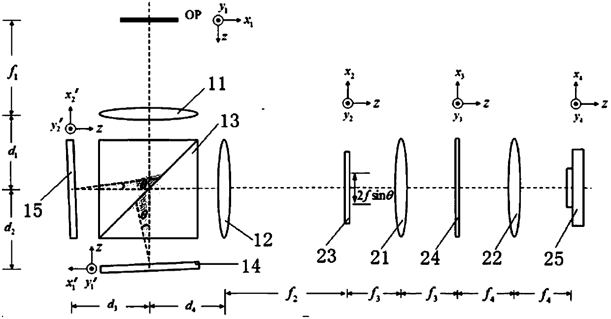
[0029] like figure 2 As shown, a phase recovery system based on light intensity transmission measurement and calculation is mainly formed by cascading two 4f system optical path structures, wherein the first 4f system is mainly composed of the first Fourier transform lens 11 (with a focal length of f 1 ), the second Fourier transform lens 12 (the focal length is f 2 ), dichroic prism 13, the first spatial light modulator 14 and the second spatial light modulator 15, the second 4f system mainly consists of the third Fourier transform lens 21 (the focal length is f 3 ), the fourth Fourier transform lens 22 (the focal length is f 4 ), a transparent imaging screen 23, a sinusoidal grating 24 and a CCD25. This embodiment follows the standard 4f system, ie setting f 1 = f 2 and f 3 = f 4 , for the convenience of description, set f at the same...


PUM


Abstract

The invention provides a phase recovery system based on light intensity transmission measurement and calculation. The system comprises a first 4f system and a second 4f system; the first 4f system ismainly composed of a first Fourier transform lens, a second Fourier transform lens, a light splitting prism, a first spatial light modulator and a second spatial light modulator; and the second 4f system is mainly composed of a third Fourier transform lens, a fourth Fourier transform lens, a transparent imaging screen, a sine grating and a CCD. According to the invention, optical measurement and calculation are combined, a differential image is obtained directly via an optical system instead of collecting under-focus and over-focus images and using the under-focus and over-focus images as approximation of intensity differential terms, it can be ensured that the resolution of the differential image matches the CCD, errors caused by mechanical movement of the CCD in a traditional system areovercome, and the problem that images collected by an SLM based single-frame measurement system are low in resolution is solved.

Description

technical field [0001] The invention relates to the technical field of optical measurement and biomedical imaging, in particular to a phase recovery system based on measurement and calculation of light intensity transmission. Background technique [0002] Holography can effectively record the phase information of the original object light field by using the principle of interference. However, interferometry puts forward high requirements on the coherence of the light source, the construction of the optical path system, and the experimental environment during operation, which is not conducive to the application in optical measurement and biomedical imaging. Therefore, it is very important to find a method of non-interferometric phase acquisition. The phase recovery technology based on the Transport of Intensity Equation (TIE) provides an important means of non-interference phase acquisition. It recovers the phase of the light field by measuring the intensity of multiple pla...

Claims


Application Information

Patent Timeline
Patent Type & Authority Applications(China)
IPC IPC(8): G02B27/10G02B27/42
CPCG02B27/10G02B27/42
Inventor 沈川朱钦钦洪青青程鸿张成韦穗
Owner ANHUI UNIVERSITY
Why Eureka
Try Eureka