
Three-dimensional planta pedis scanning device and method based on single-camera four-step grating phase shift method
A single-camera, three-dimensional scanning technology, applied in the field of biomedicine, can solve the problems of long scanning period, low precision, and human foot scanning, etc., and achieve the effect of improving scanning accuracy and speed, small amount of image data, and fast scanning speed.
- Summary
- Abstract
- Description
- Claims
- Application Information
AI Technical Summary
Problems solved by technology
Method used
Image

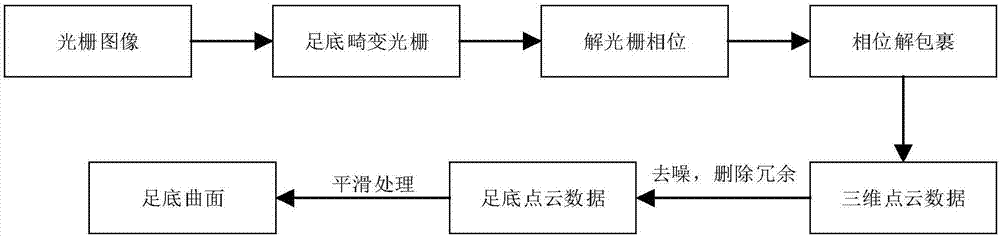
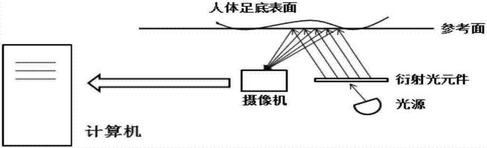
Examples
Embodiment Construction
[0052] The specific implementation manners of the present invention will be further described in detail below in conjunction with the accompanying drawings and embodiments.
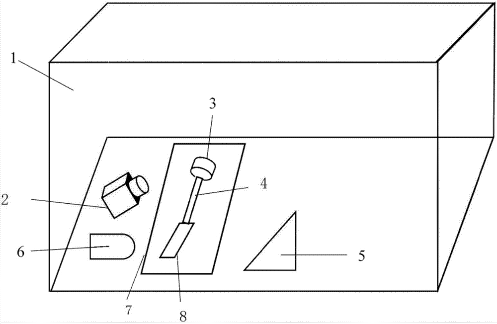
[0053] refer to image 3 , a plantar three-dimensional scanning device based on a single-camera four-step grating phase-shift method, comprising a box body 1 with a transparent top, a transverse support plate 7 is arranged in the middle of the box body 1, and a sinusoidal grating 8, servo The motor 3 and the single-axis ball screw linear slide 4, the sinusoidal grating 8 is connected to the control end of the servo motor 3 through the single-axis ball screw linear slide 4, and the bottom of the box 1 and directly in front of the sinusoidal grating 8 is provided with a The laser light source 6 adapted to the sinusoidal grating 8 is provided with an image reflection mirror 5 in front of the sinusoidal grating 8 and the laser light source 6 , and a single camera 2 is also provided on the box 1 .
[0054] Th...
PUM
 Abstract
Description
Claims
Application Information