Temporary shelter system

a shelter system and temporary technology, applied in the field of temporary shelter systems, can solve the problems of unsatisfactory widespread use or operations, the characteristics of conventional armored shelter types are comparatively heavy and expensive, and the shelter types are not typically provided protection from direct and indirect effects, etc., to maximize the efficiency of delivery, assembly and extraction during deployment, and the trajectory is high

Active Publication Date: 2016-03-08
NEAD DANIEL MORRELL
View PDF18 Cites 10 Cited by
  • Summary
  • Abstract
  • Description
  • Claims
  • Application Information

AI Technical Summary

Benefits of technology

[0008]In this effort, the design of the shelter is governed by the following parameters. 1) The shelter provides high trajectory threat mitigation through a unique protection system that detonates, absorbs, and deflects blast energy away from the shelter. 2) The shelter envelope makes use of a novel fill technique and associated apparatus in order to provide customizable protection. This technique uses manpower-based fill and compaction methods in order to maximize efficiency of delivery, assembly and extraction during deployment. 3) The partially assembled structure may be delivered and extracted via helicopter or ground transport. 4) The design enh

Problems solved by technology

These shelter types do not typically provide protection from direct and indirect fire.
In cases where protection is provided, conventional armored shelter types are comparatively heavy and expensive structures.
These characteristics are not ideal for widespread use or for operations requiring rapid deployment and mobi

Method used


Image

  • Temporary shelter system
  • Temporary shelter system
  • Temporary shelter system

Examples


first embodiment

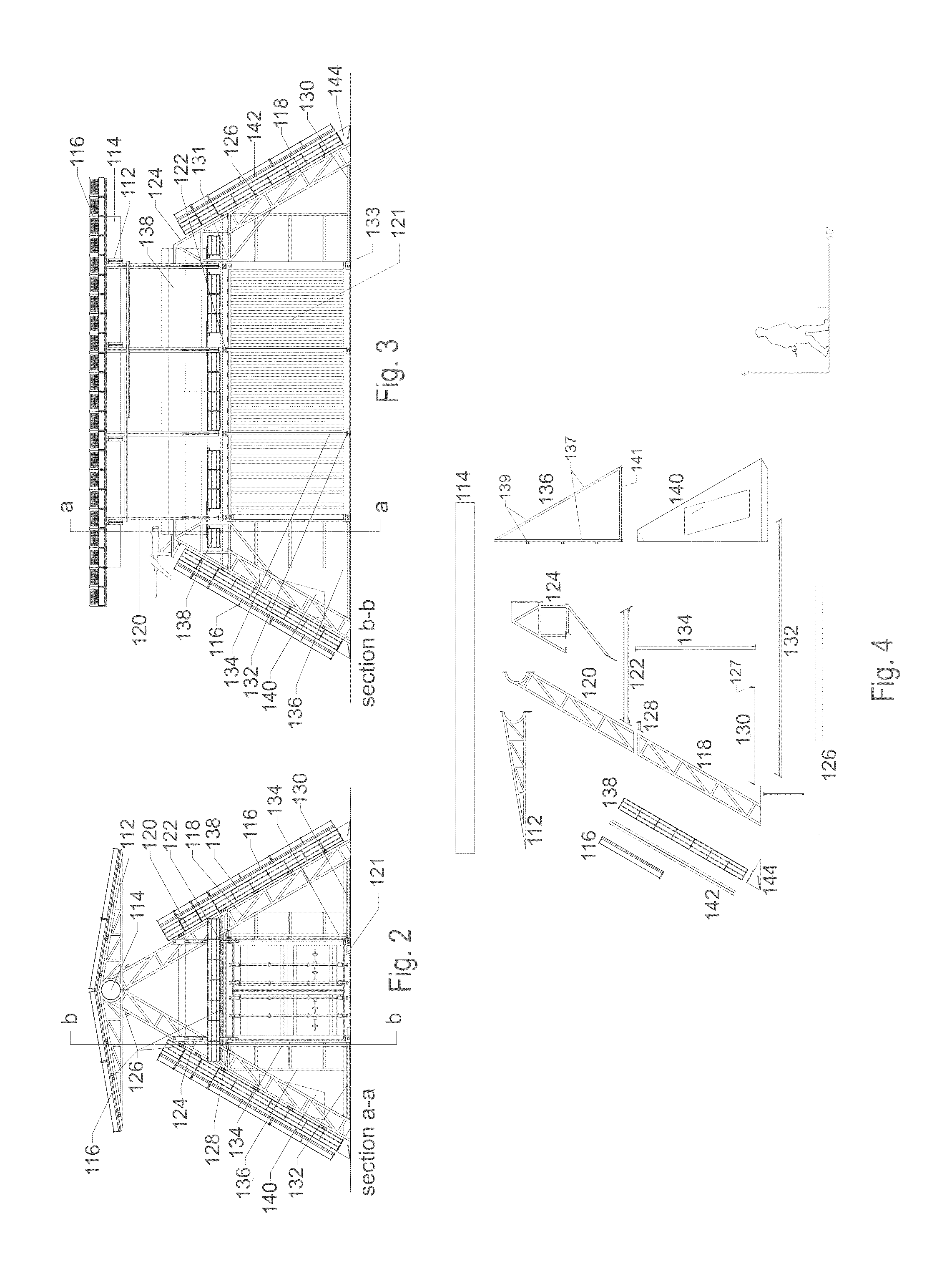
[0106]Non-Conex Based Embodiments: The structural performance of the framing system in the non-conex based shelter embodiments are self-contained and independent of the conex structural performance as shown in FIGS. 11, 12, 13 and 14. As the non-conex based embodiments are not tied to the dimensions of the conex unit, they may be of a significantly smaller or larger dimension and footprint when compared to the conex based embodiment. In the non-conex based framing system, shown in FIGS. 11 and 12, the plurality of main A-frames, the plurality of secondary lateral members, and four triangular corner frames are of similar form and function to that of the conex based embodiment that is shown in FIGS. 2, 3, 4, 5, and 6. The main A-frames are those A-frames that straddle the protected area of the shelter. The structural differences between the conex based embodiment and the non-conex based embodiment are the non-conex based embodiment's alternative form of end framing 172, 194, the absen...

second embodiment

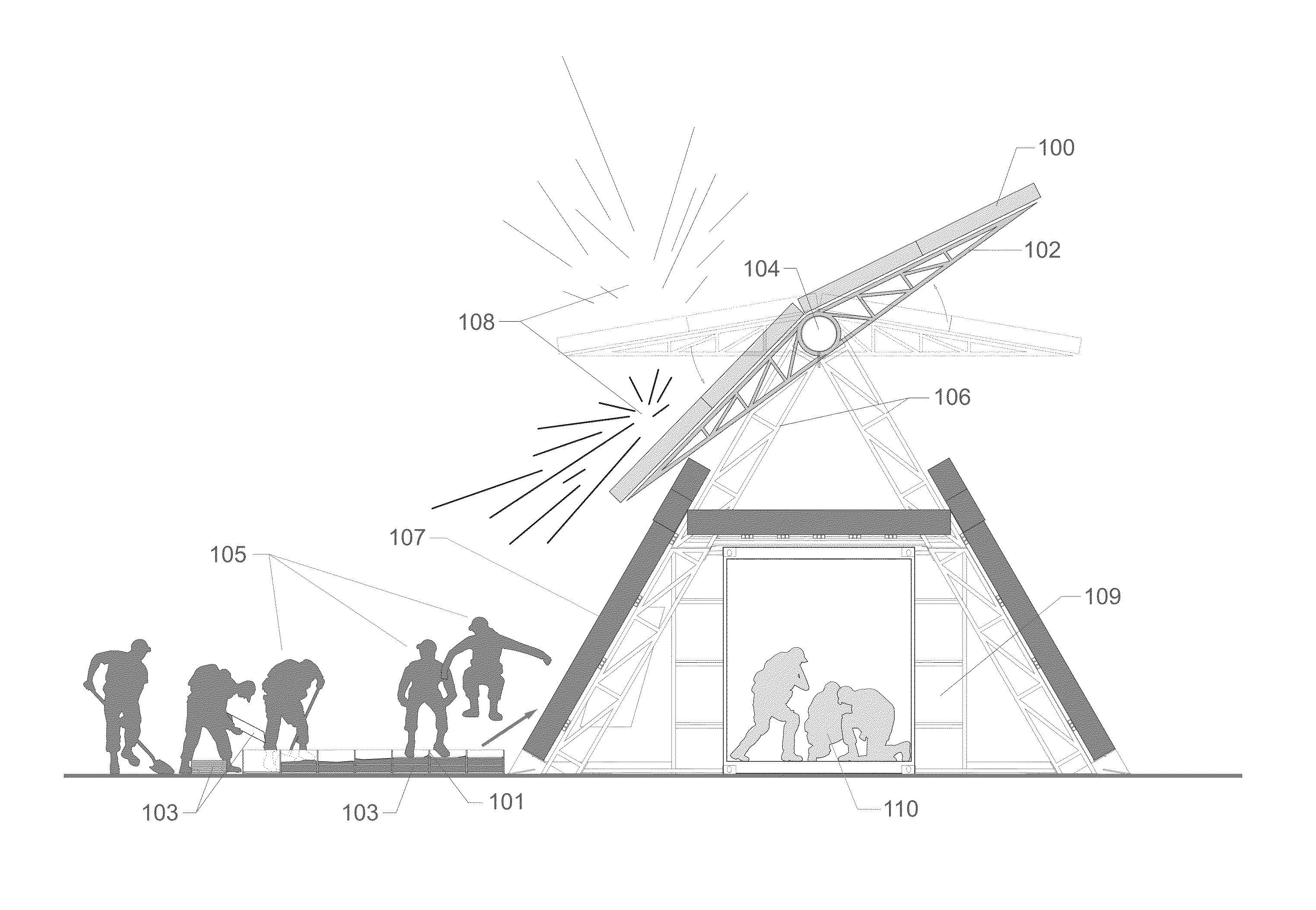
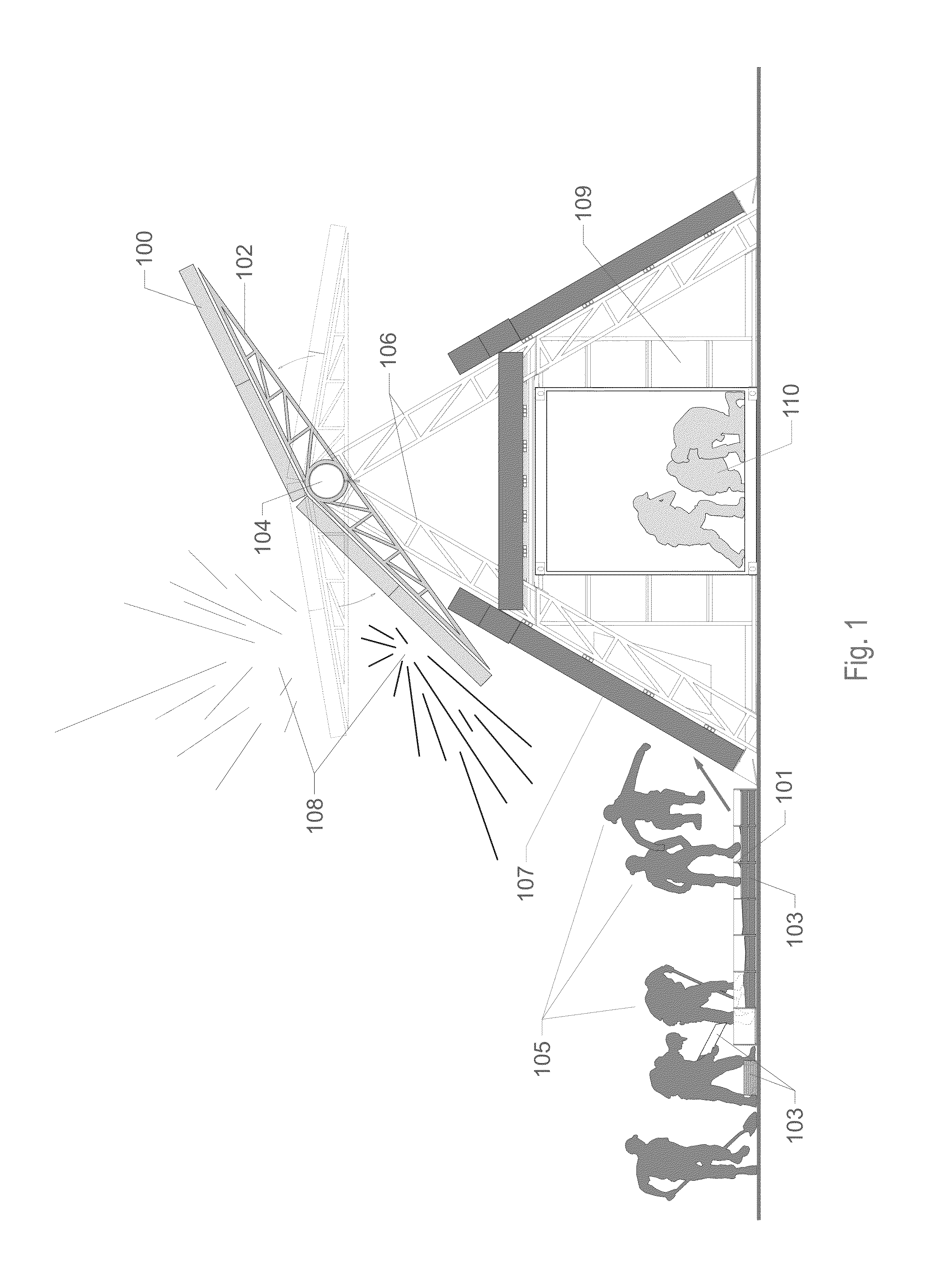
[0108]In a non-conex based temporary shelter system, a plurality of ports with hinged shutters 188, 187 are positioned at the tops of the sloped vertical vessels 191 that compose the wall elements of the shelter. The ports are used for lighting, ventilation, weapon use, and emergency egress. The opening for the port is created by a gap between the topmost end-face of the vertical vessels 191 and the cylindrical axle 192 at the apex of the A-frame. When folded out, the shutter 187 rests horizontally on top of the vessel to protect personnel from threats 196 deflected from the sloped sides of the envelope. When folded in to the closed position, the free end of each shutter rests on a lateral member 190 below the axle-tank. The restrained end of the shutter has a pin-connection 193 attachment to the top of the vessel envelope wall. The port is at an appropriate height for personnel to observe the exterior environment if standing on the ground surface or if atop an object on ground surf...


PUM


Abstract

A shelter system is disclosed which comprises three central elements. A rotatable barrier element provides protection from incoming ballistic threats. The barrier functions on the principle of detonating, absorbing, and deflecting incoming threats away from a designated area of the shelter. A protective envelope element utilizes a compartmentalized vessel, two containment components, and a strata of alternating compacted fill and interstitial plate layers; the strata is enclosed within the vessel and two containment components. The interstitial plates serve a dual role in providing a compaction surface in the fill method and layering for the mitigation of ballistic threats. The design of the vessel permits each vessel to be filled while positioned flat on the ground surface; once filled and sealed, multiple vessels may be re-positioned in vertical, horizontal, sloped, or spanning arrangements. An A-frame based structural element functions as the fulcrum for the rotatable barrier and as the mount for the envelope trays. The structural system has an option of fastening to the framing system of the standard conex container.

Description

RELATED PATENT APPLICATIONS[0001]This application is based upon and claims the priority of provisional patent application No. 61 / 729,670, filed on Nov. 26, 2012, incorporated herein by reference in its entirety.FIELD OF THE INVENTION[0002]This invention is directed to temporary shelter systems including a rotatable barrier system, an envelope system with material-fill apparatus, and an associated A-frame based structural system for both the rotatable barrier and the envelope.BACKGROUND OF INVENTION[0003]In combat, civil defense, civil unrest, border security and disaster related situations, there is often a need for a temporary shelter that can be rapidly deployed, assembled, and extracted. In these situations, the shelter must provide protection from enemy and / or environmental threats. In some instances it is advantageous that the shelter be delivered and extracted via helicopter. Contemporary military shelter practices are varied. Common shelter types include tent structures, plyw...

Claims


Application Information

Patent Timeline
IPC IPC(8): E04H9/10E04H9/04
CPCE04H9/10E04H9/04Y10S52/12Y10S52/14
Inventor NEAD, DANIEL, MORRELL
Owner NEAD DANIEL MORRELL
Why Eureka
Try Eureka