Glass run
A technology for glass chute and door glass, which is applied in mechanical equipment, transportation and packaging, engine components, etc. It can solve the problems of deterioration of the installation state of the installation part and decrease of sealing performance, so as to improve the appearance quality, avoid step difference and improve the sealing performance Effect
- Summary
- Abstract
- Description
- Claims
- Application Information
AI Technical Summary
Problems solved by technology
Method used
Image
Examples
no. 1 example
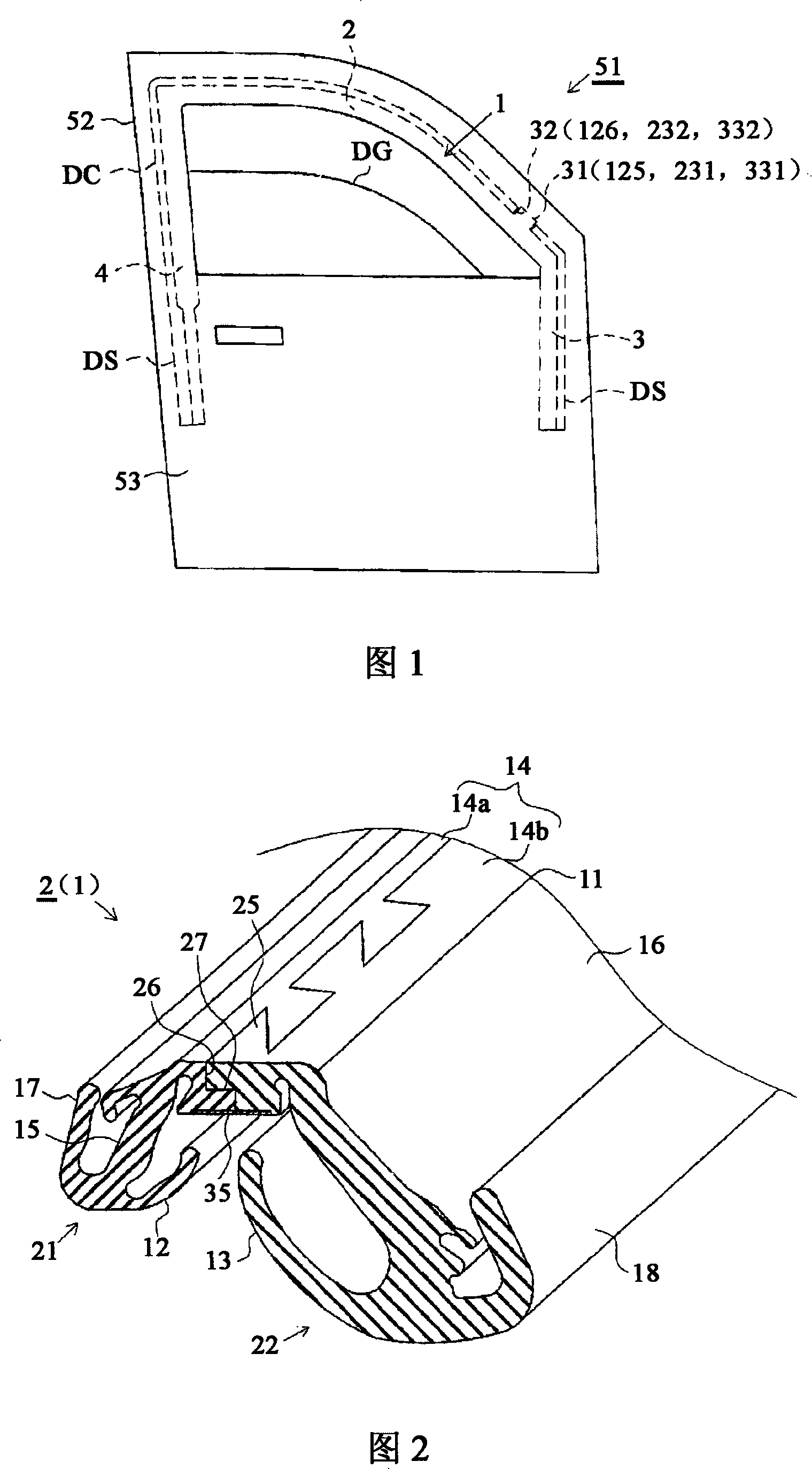
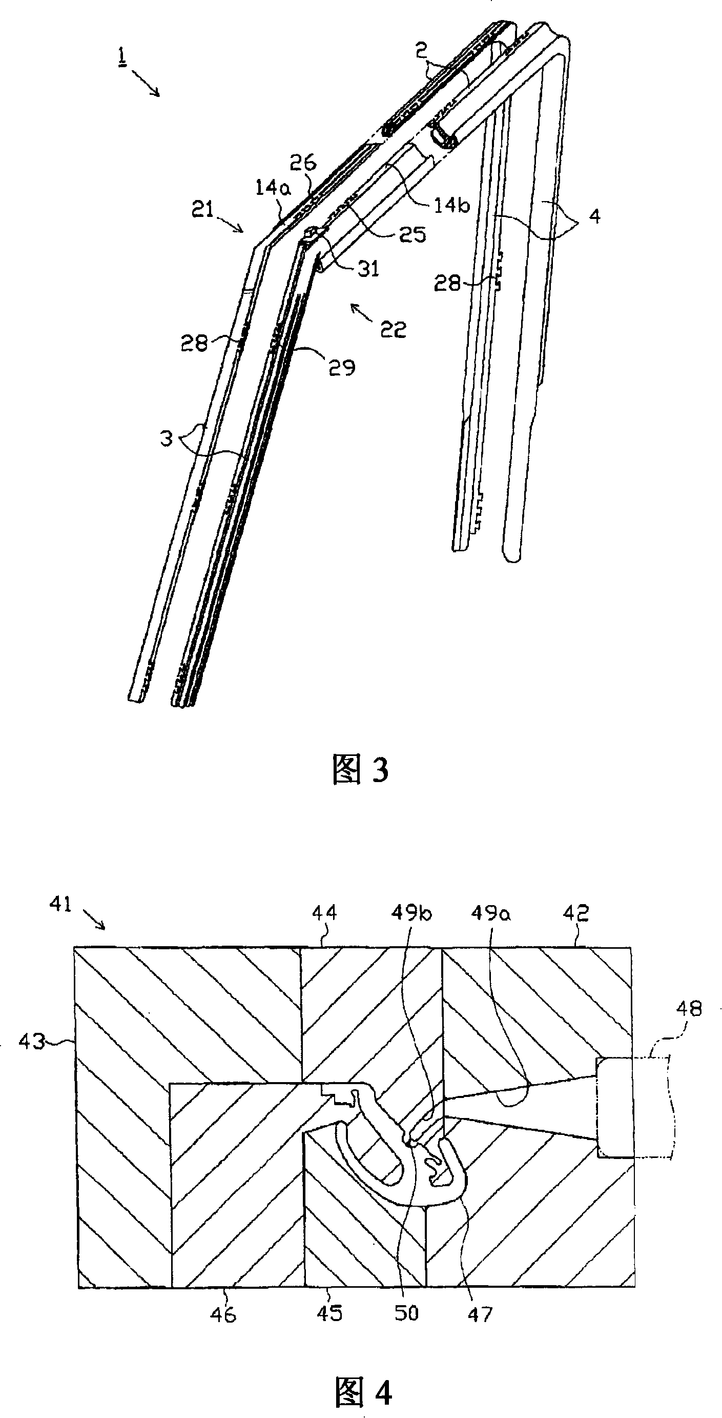
[0048] The first embodiment will be described below with reference to the drawings. FIG. 1 is a schematic front view of a vehicle door structure. Fig. 2 is a partial axonometric view of the upper side of the glass run. Figure 3 is an exploded isometric view of the glass run.
[0049] As shown in FIG. 1 , a vehicle door 51 (the front door in the drawing) includes a glass run 1, which is used to guide the lift of the door glass DG, and when the door glass DG is raised to close the window, The gap between the outer periphery of the glass DG and the door frame 52 provides a seal. More specifically, the glass run channel 1 includes an upper side portion 2, a front vertical side portion 3 and a rear vertical side portion 4, the upper side portion 2 constituting a portion corresponding to the upper edge portion of the door glass DG, and the front vertical side portion 3 constitutes a portion extending downward from the front end portion of the upper side portion 2 and corresponds ...
no. 2 example
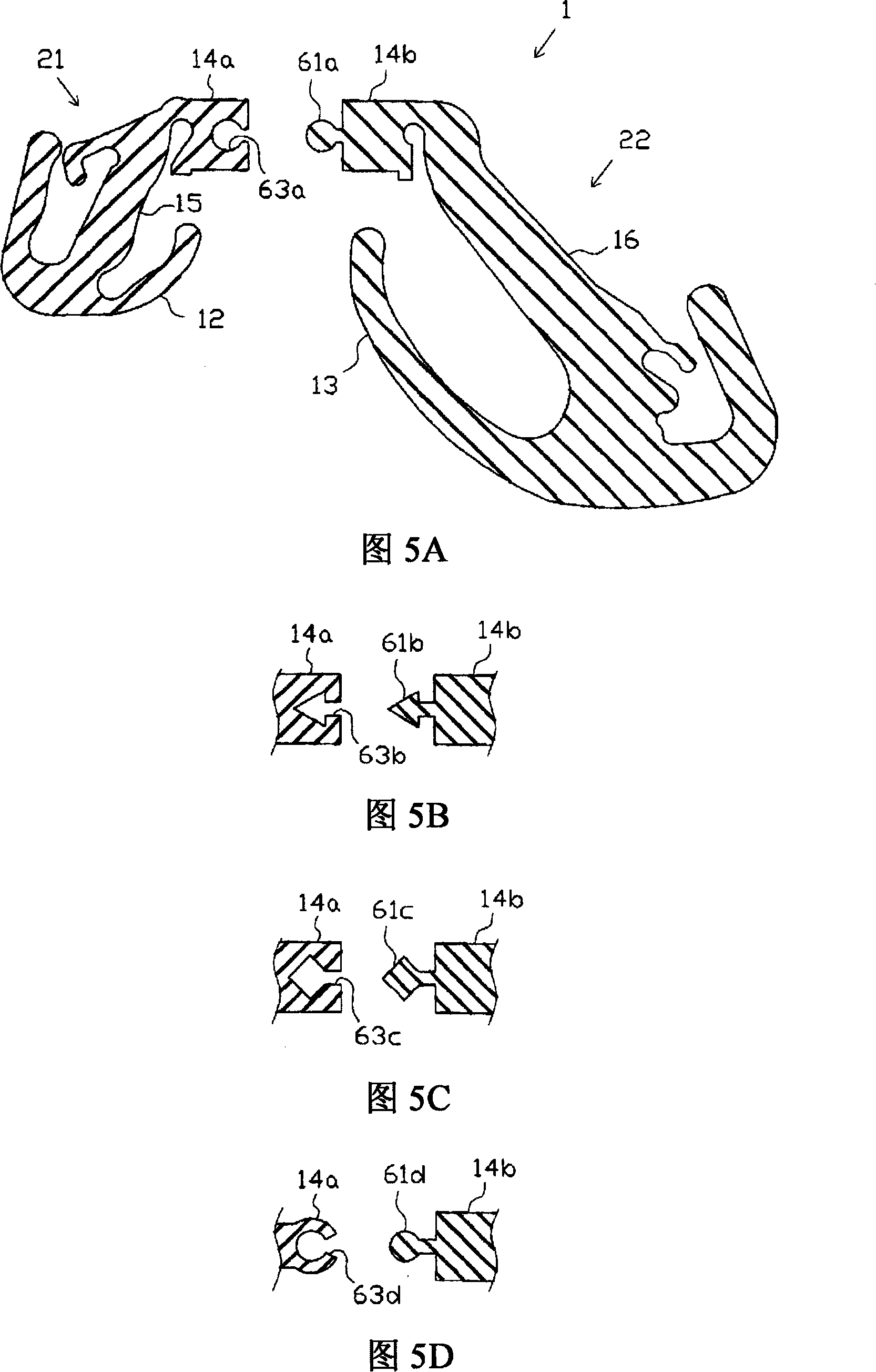
[0088] A second embodiment will be described below with reference to the drawings. Fig. 10 is a sectional view showing the upper side of the glass run. Fig. 11 is a sectional view showing the rear vertical side of the glass run in an exploded state. Figure 12 is an exploded isometric view of the glass run.
[0089] According to the second embodiment, as shown in FIG. 10 , the upper side portion 2 includes a main body portion 111 and a vehicle exterior seal lip 112 and a vehicle interior seal lip 113 . The main body portion 111 includes a bottom 114 fitted to the channel portion DC and an exterior side wall portion 115 and an interior side wall portion 116 extending from the bottom portion 114, and constitutes a substantially U-shaped cross section as a whole. The exterior seal lip 112 extends approximately from the distal end of the exterior wall portion 115 toward the inner periphery of the body portion 111 , and the interior lip seal 113 extends approximately from the dist...
no. 3 example
[0122] A third embodiment will be described below with reference to the drawings. Fig. 20 is a sectional view showing a state in which a glass run is attached to a window frame portion. Fig. 21 is a cross-sectional view of the glass run channel in an exploded state.
[0123] As shown in FIG. 20 and FIG. 21 , the upper side part 2 includes: a main body part 211 , a seal lip 212 on the outside of the vehicle, and a seal lip 213 on the inside of the vehicle. The main body portion 211 includes a bottom portion 214 fitted to the channel portion DC, and an outer side wall portion 215 and an inner side wall portion 216 extending from the bottom portion 214 so as to constitute a substantially U-shaped cross section as a whole. The exterior seal lip 212 extends toward the inner peripheral side of the body portion 211 from the tip of the exterior wall portion 215 , and the interior lip seal 213 extends toward the inner periphery of the body portion 211 from the tip of the interior wall...
PUM
 Abstract
Description
Claims
Application Information
 - R&D
- Intellectual Property
- Life Sciences
- Materials
- Tech Scout
- Unparalleled Data Quality
- Higher Quality Content
- 60% Fewer Hallucinations
Browse by: Latest US Patents, China's latest patents, Technical Efficacy Thesaurus, Application Domain, Technology Topic, Popular Technical Reports.
© 2025 PatSnap. All rights reserved.Legal|Privacy policy|Modern Slavery Act Transparency Statement|Sitemap|About US| Contact US: help@patsnap.com


