Inductor

An inductor and electrode technology, which is applied in the field of surface mount inductors, can solve the problems of limiting the miniaturization of products and insufficient use of product space, and achieve the effect of low profile, improved electrical characteristics, and accuracy.

Inactive Publication Date: 2008-04-02
SUMIDA ELECTRIC H K COMPANY
View PDF2 Cites 19 Cited by
  • Summary
  • Abstract
  • Description
  • Claims
  • Application Information

AI Technical Summary

Problems solved by technology

Although this invention provides an inductor that can be applied to hot air soldering and reflow soldering at the same time, due to the arrangement of the lead groove 4, the lead wire of the coil 5 must occupy the horizontal direction when it is drawn out to the terminal 3. A certain space makes the space of the product not fully utilized, which also limits the miniaturization of the product

Method used


Image

  • Inductor
  • Inductor
  • Inductor

Examples


Embodiment 1

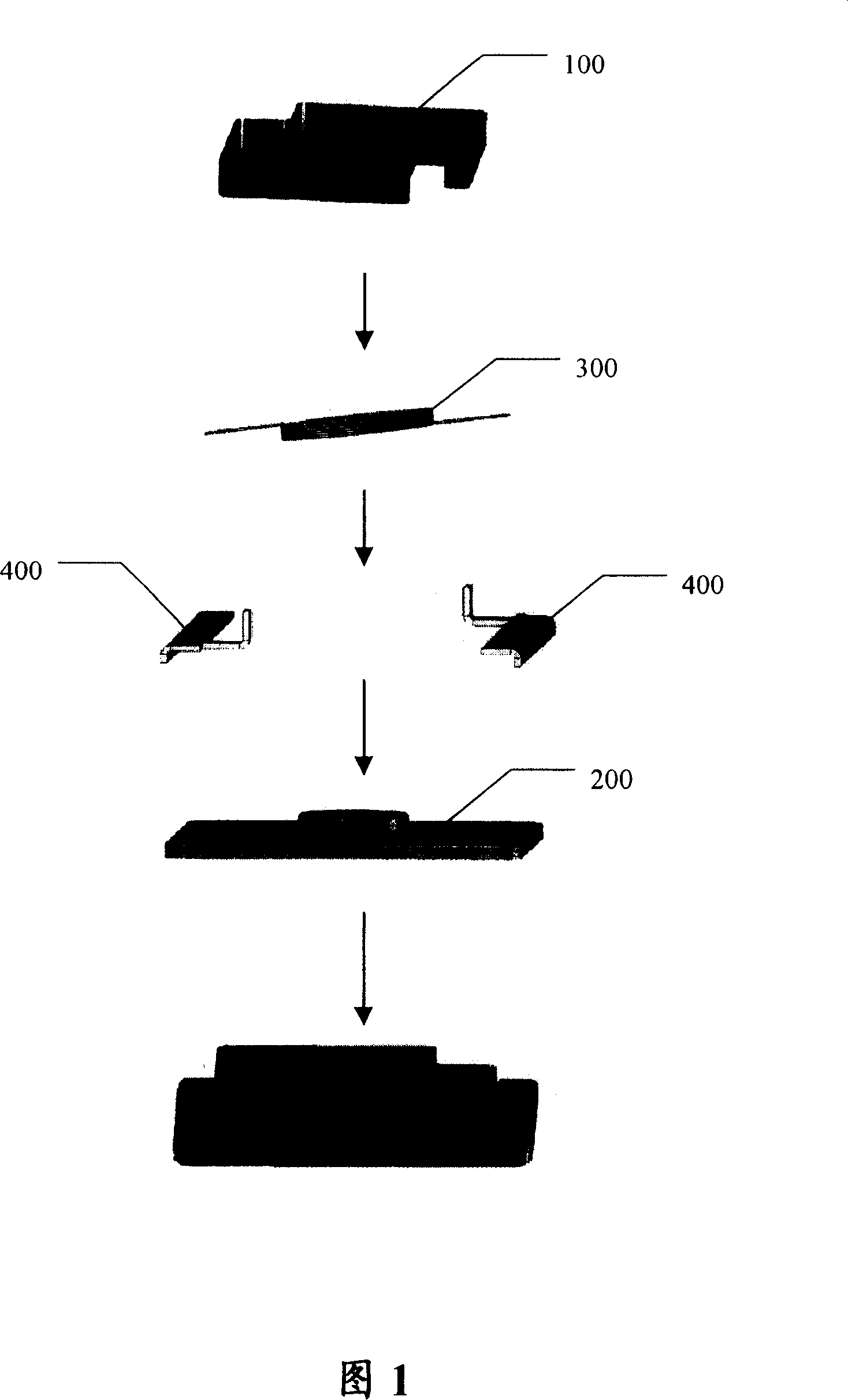
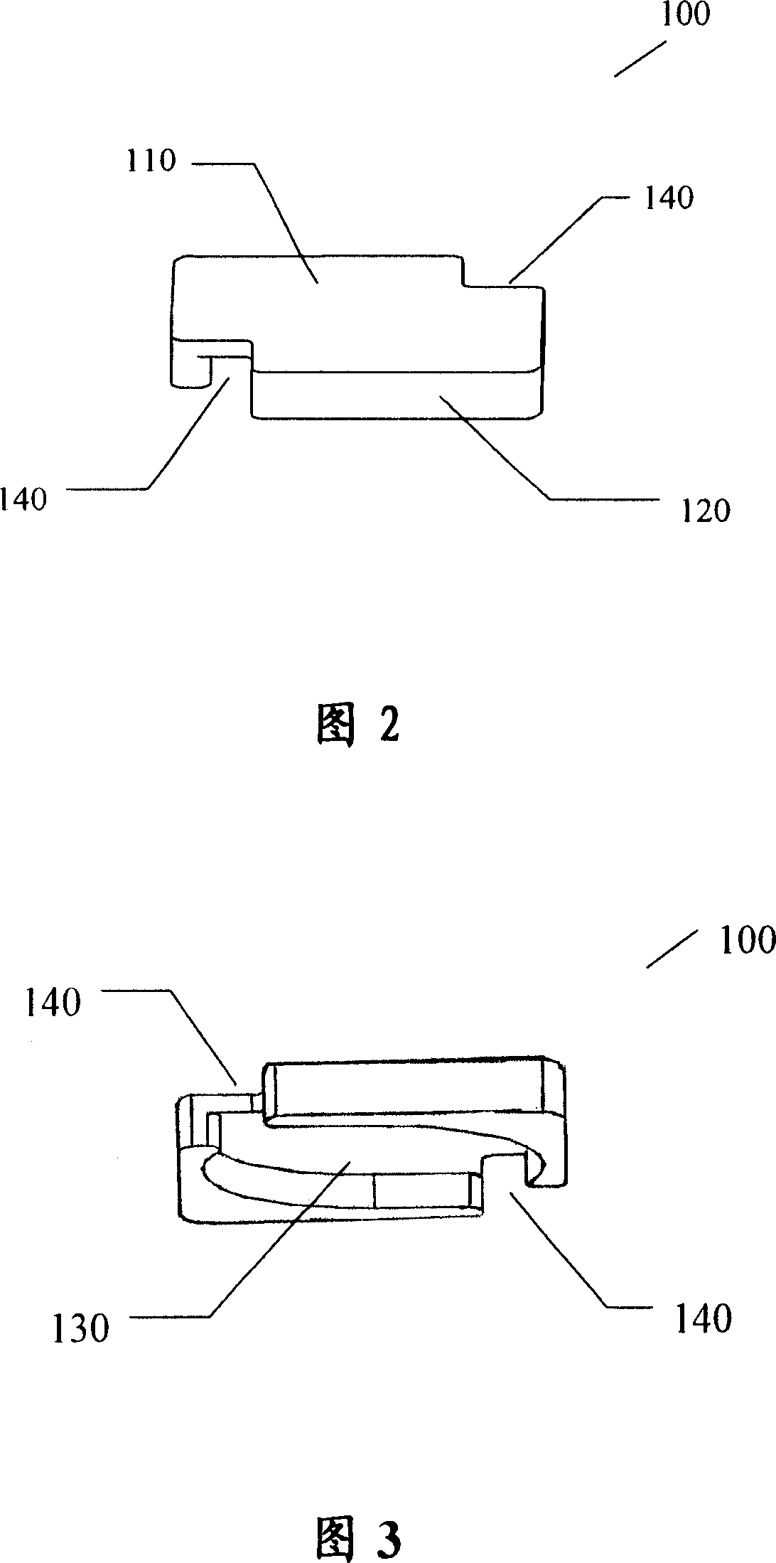
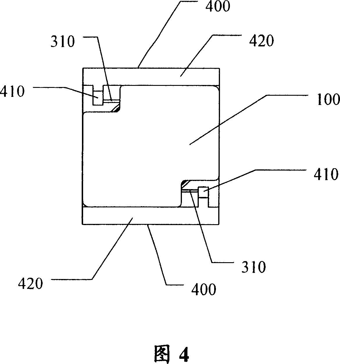
[0030] Embodiment 1: As shown in FIG. 1 , the inductor according to this embodiment includes: a flat rectangular parallelepiped magnetic cap 100 , a substrate 200 , a coil 300 and two electrodes 400 . As shown in FIG. 2 , the magnetic cap 100 is composed of a top wall 110 and a side wall 120 for forming a cylindrical cavity 130, see FIG. The two notches 140 passing through the side wall 120 and the top wall 110 of the magnetic cap, see FIG. 2 and FIG. 3 , are used to lead out the two lead ends 310 of the coil 300 to connect with the electrode 400 , see FIG. 4 . As shown in Figure 5, a cylindrical magnetic core 210 corresponding to the cavity 130 of the magnetic cap 100 is provided on the substrate 200, preferably the cylindrical magnetic core 210 is perpendicular to the substrate 200 and integrally formed with the substrate 200; the coil 300 has two lead ends 310 , and the coil 300 can be sleeved on the magnetic core 210 . As shown in Figure 5, the electrode 400 includes a co...

Embodiment 2

[0034] Embodiment 2: As shown in FIG. 7, the difference between the inductor of this embodiment and the inductor of Embodiment 1 is that two cylindrical magnetic cores 210 are arranged on the substrate 200; the magnetic cap 100 is a flat cuboid Shaped, the side wall and the top wall of the magnetic cap 100 form a cavity that can accommodate two cylindrical magnetic cores 210 behind the coils 300 respectively; The notch 140 of the side wall and the top wall of the cap 100 .

Embodiment 3

[0035] Embodiment 3: As shown in FIG. 8 and FIG. 9, the inductor of this embodiment is similar to the inductor of Embodiment 1, and a cylindrical magnetic core 210 is arranged on the substrate 200; the magnetic cap 100 is a flat cuboid shape, The side wall and the top wall of the magnetic cap form a cylindrical cavity. However, the difference between the inductor of this embodiment and the inductor of Embodiment 1 is that there are notches penetrating through the side wall and the top wall of the magnetic cap at the four edges of the rectangular parallelepiped magnetic cap 100 respectively, wherein the The coil 300 connected to the magnetic core 210 has two windings, and the four lead ends of the coil 300 are led out from the four gaps respectively to connect with the four electrodes 400 respectively.


PUM


Abstract

The invention discloses an inductor, comprising a baseplate which is provided with at least one magnetic core, at least one coil which can be socket jointed on the magnetic core, a magnetic cap consisting of a top wall and a side wall to form at least one hollow chamber for containing the magnetic core and coil, and an electrode arranged on the baseplate for connecting a lead terminal of the coil and an external circuit, wherein, the magnetic cap is provided with a gaping place going through the side wall and top wall of the magnetic cap, and the gaping place is used for leading out the lead terminal of the coil to be connected with the electrode. The invention is applicable to various electronic aids, in particular to the electronic products needing to take full advantage of space such as mobile phones and notebook PC.

Description

technical field [0001] The invention relates to an electronic component, in particular to a surface mounted inductor. Background technique [0002] As a main electronic component, the inductor has been widely used in the design of various electronic circuits, and it is an indispensable component to realize many circuit functions. [0003] With the development trend of miniaturization and light weight of various electronic equipment, the electronic components that constitute electronic equipment, including inductors, are also constantly developing in the direction of miniaturization and light weight. For this reason, on the basis of traditional inductors, those skilled in the art have done a lot of research and development in terms of production technology and product structure, and have designed a variety of inductors suitable for production and practical applications. device. For example, Japanese Patent Laid-Open No. 2003-173915 discloses a small-sized choke coil having ...

Claims


Application Information

Patent Timeline
Patent Type & Authority Applications(China)
IPC IPC(8): H01F17/04H01F27/00
Inventor 林有根王金盛
Owner SUMIDA ELECTRIC H K COMPANY
Why Eureka
Try Eureka