
Eureka
For R&D, Eureka makes reading and utilizing patents & technical documents easy.
Eureka AIR
Designed for self-driven R&D workflows. Generate viable solutions, solve complex R&D challenges, empower your innovation with AI.

Eureka Materials
Designed for material experts only. Revolutionize your material R&D, from search, analyze, to developing new materials.

TechResearch
Generate reliable direction feasibility study reports for your R&D in just a few steps.

TechSeek
Discover and master advanced knowledge NOW. Basics, ideas, possibilities, all at once.

TechMind
As an expert in R&D Theories, TechMind can generates customized viable solutions instantly.

TechRisk
Analyze your overall solution with one click, know your potential R&D risks in advance.

TechMonitor
Get weekly tech updates, stay abreast of the latest tech innovations and key insights.
Double-rotating shaft electric motor
A dual-shaft and casing technology, applied in electrical components, electromechanical devices, electrical components, etc., can solve the problem of not being able to meet special requirements, and achieve the effect of improving efficiency and wide adaptability
- Summary
- Abstract
- Description
- Claims
- Application Information
AI Technical Summary
Problems solved by technology
Method used
Image

Examples
Embodiment
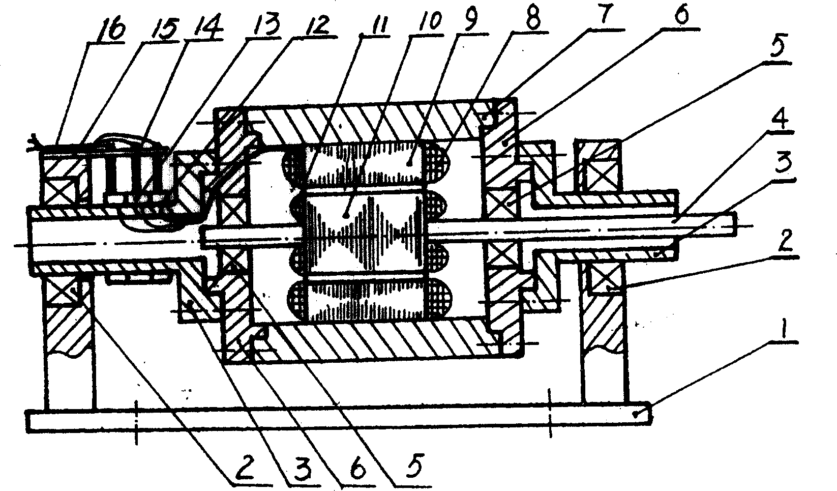
[0007] Embodiment: A double-rotating shaft motor, the outer rotor coil 8 is embedded in the slot of the outer rotor core 9, the outer rotor core is matched with the casing 7, the inner rotor coil 11 is embedded in the slot of the inner rotor core 10, the inner rotor Iron core 10 and coil 11 are set on the outer rotor iron core 9 and coil 8 with a small gap in between. The inner rotor shaft 4 is fixed on the end cover 6 through the inner rotor bearing 5, and the end cover 6 is fixed on the casing 7. The outer rotor One end of the pump 3 is fixed on the end cover 6, the other end is fixed on the base 1 through the outer rotor bearing 2, the brush holder 15 is fixed on the base 1, and the slip ring 13 connects the outer rotor shaft 3 and the slip ring 13 through the insulation 12. After being insulated, they are fixed on the outer rotor shaft 3, and the power supply is sent into the outer rotor coil 8 through the lead wire 16, the carbon brush 14 and the slip ring 13.
PUM
 Abstract
Description
Claims
Application Information
 - R&D Engineer
- R&D Manager
- IP Professional
- Industry Leading Data Capabilities
- Powerful AI technology
- Patent DNA Extraction
Browse by: Latest US Patents, China's latest patents, Technical Efficacy Thesaurus, Application Domain, Technology Topic, Popular Technical Reports.
© 2024 PatSnap. All rights reserved.Legal|Privacy policy|Modern Slavery Act Transparency Statement|Sitemap|About US| Contact US: help@patsnap.com