Fan system, electric motor, and claw-pole motor

A fan system, salient-pole technology, applied in the field of fan systems, can solve the problems of low vibration and noise, and achieve the effect of low vibration and noise

Inactive Publication Date: 2008-04-02
HITACHI IND EQUIP SYST CO LTD
View PDF5 Cites 5 Cited by
  • Summary
  • Abstract
  • Description
  • Claims
  • Application Information

AI Technical Summary

Problems solved by technology

[0015] In order to solve the above-mentioned problems, the object of the present invention is to provide a fan system and motor, which reduces the axial length of the fan motor only as a part that contributes to torque generation, has high efficiency, low vibration and noise, and has no electric current. Eclipse problem

Method used


Image

  • Fan system, electric motor, and claw-pole motor
  • Fan system, electric motor, and claw-pole motor
  • Fan system, electric motor, and claw-pole motor

Examples


Embodiment 1

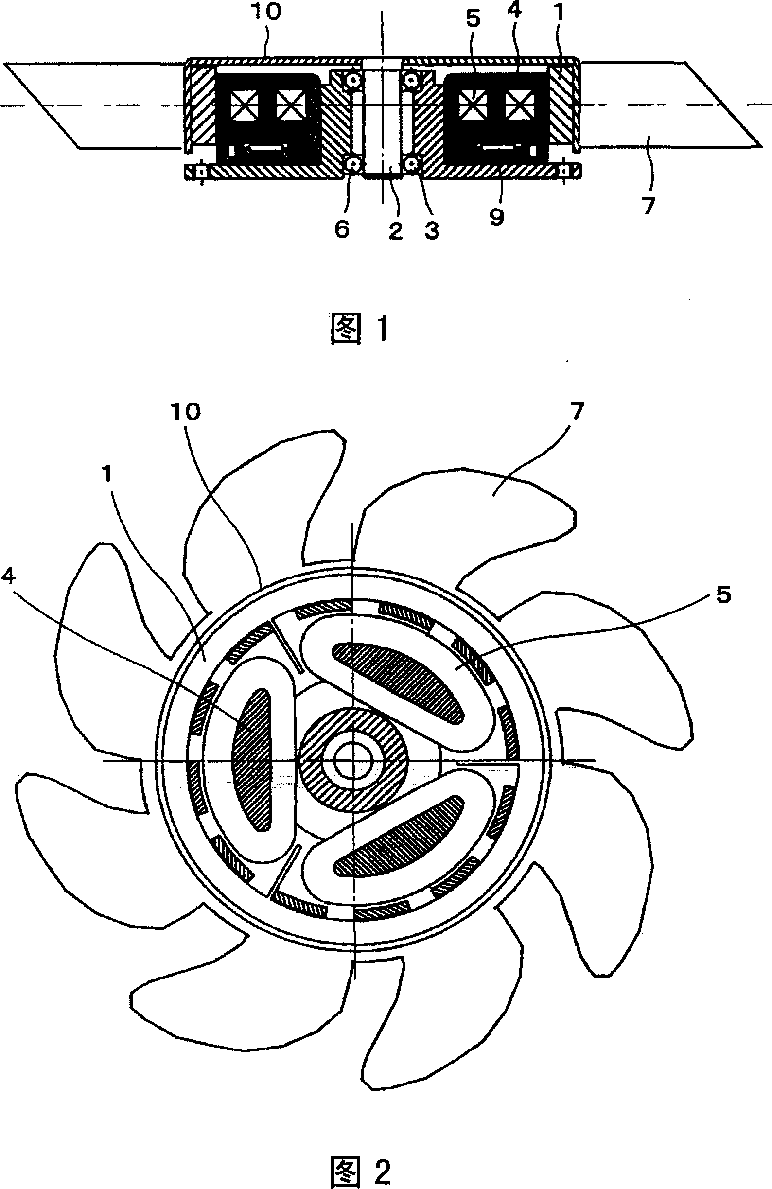
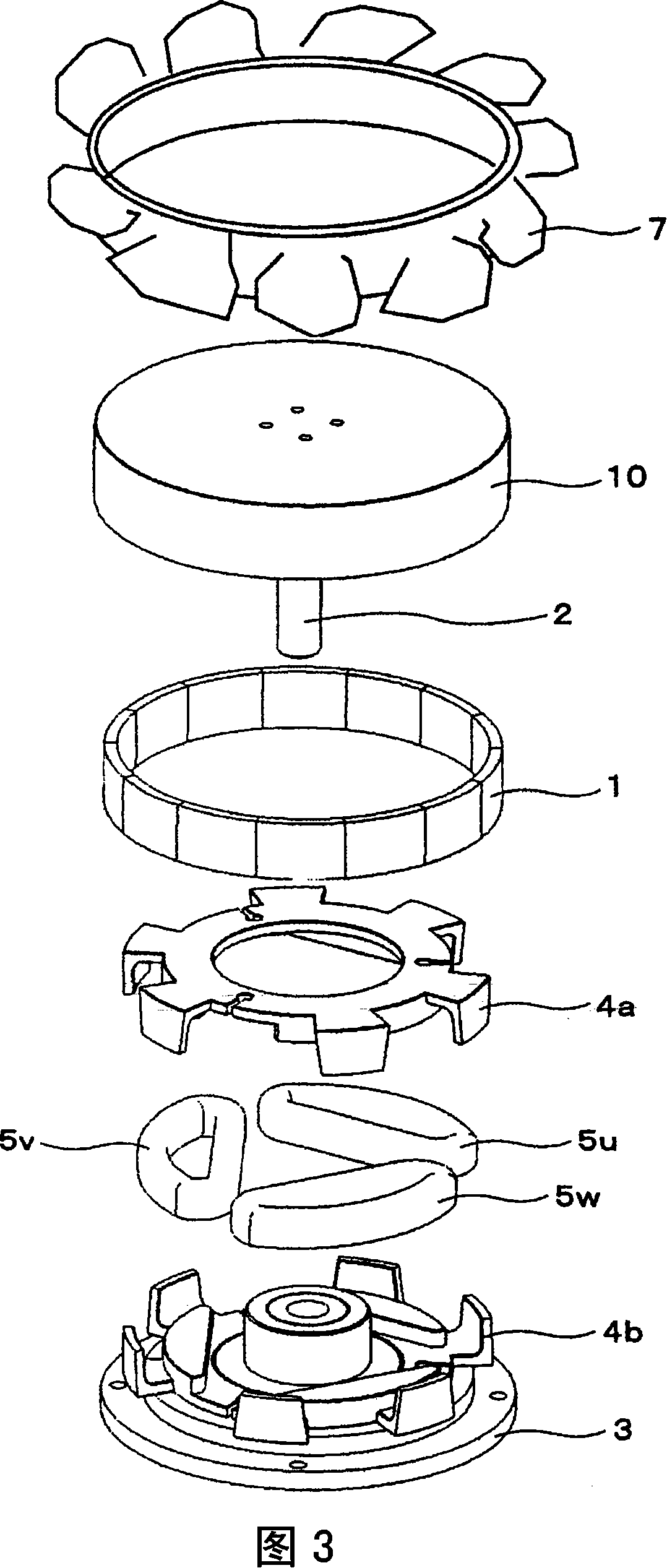
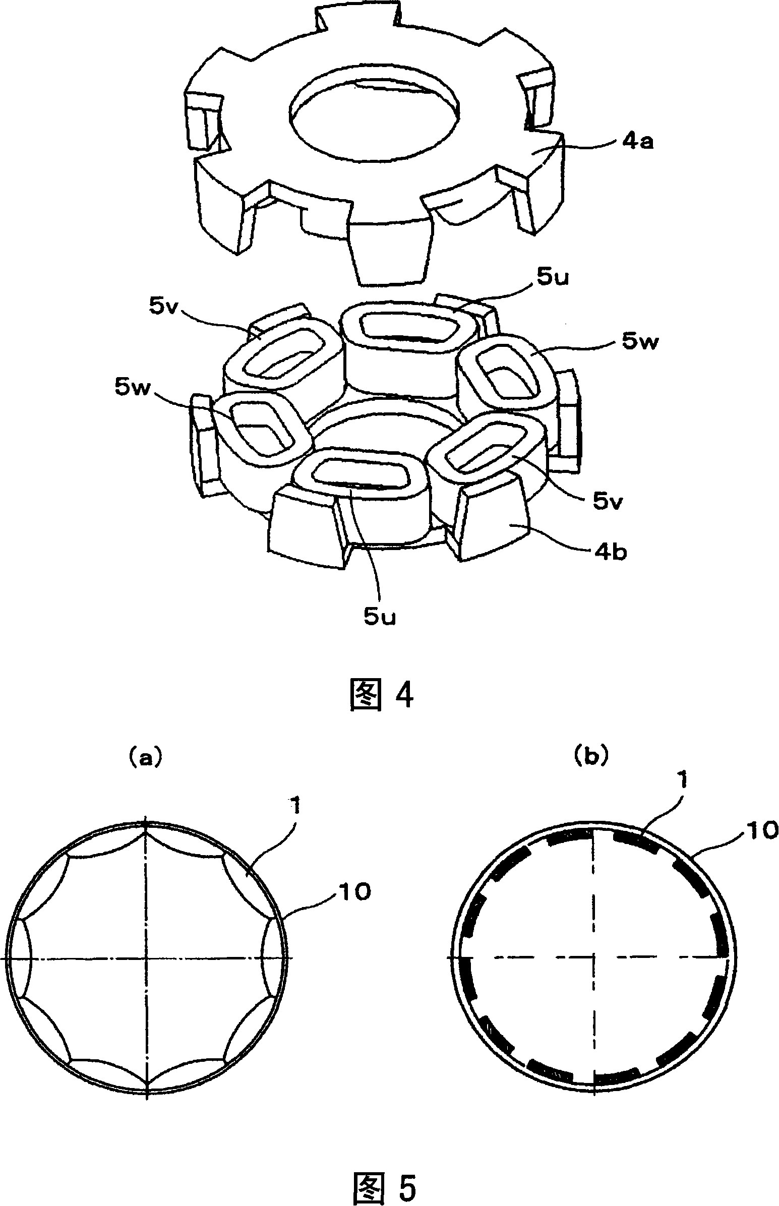
[0039] Fig. 1 shows the structure of the thin fan system of the present invention by means of a sectional view. The driving source is configured by arranging an outwardly rotating salient pole motor having a plurality of phase windings in one plane, and disposing blades on the outside of the yoke of the rotor. The salient pole motor has a structure in which a stator winding 5 is built inside a stator core 4, and the end of the winding is not exposed in the axial direction of the stator core. On the stator composed of the stator core 4 and the stator winding 5 , a control board 9 is mounted so as to ensure insulation by an insulating plate or the like, thereby constituting a stator assembly. The stator assembly is configured with the coaxiality and right angle of the bracket 3 holding the bearing, and the rotor yoke 10 combined with the shaft 2 held by the bearing. The magnet and the stator assembly arranged on the rotor yoke 10 pass through the gap It is rotatable on its oute...


PUM


Abstract

A fan system having a three-phase claw-pole motor comprising a stator and a rotor, wherein the three-phase claw-pole motor provides with stator coils for three phases which are arranged on one plane.

Description

technical field [0001] The present invention relates to a motor-driven fan system, an electric motor, and a salient pole motor, such as an exhaust fan, a ventilation fan, an air supply fan, and a cooling fan. Background technique [0002] Fan systems are used for cooling and air supply of general machines. Since these fan systems are mostly used for constant-time operation, high efficiency is required, while low vibration and noise and miniaturization are required. Generally, a motor is used as a driving source in these fan systems. Various drive motors are used depending on the application, and are constituted by a slot teeth motor formed by winding a stator core on which magnetic steel sheets are laminated. The fan motor is composed of the motors shown in "JP-A-2001-231192" and "JP-A-6-78486". On both axial sides of the stator core, there are windings called winding ends and the The end bracket (end bracket) that holds the bearing and is arranged in a way that the windi...

Claims


Application Information

Patent Timeline
Patent Type & Authority Applications(China)
IPC IPC(8): H02K37/12H02K5/16H02K5/24H02K1/27H02K3/28
CPCF04D25/0646F04D25/064H02K1/2786H02K7/14H02K1/145F04D25/0633F04D25/0613H02K21/22H02K2201/12H02K1/2791
Inventor 榎本裕治天野寿人伊藤元哉森永茂树正木良三惠比根一秀远山雄二
Owner HITACHI IND EQUIP SYST CO LTD
Why Eureka
Try Eureka