
Engine cylinder block lubricant oil path

A technology for engine cylinders and lubricating oil passages, which is applied in the directions of engine lubrication, engine components, and engine cooling. Simplified processing and optimal cooling and lubrication effects

Active Publication Date: 2008-04-09
CHERY AUTOMOBILE CO LTD
View PDF0 Cites 10 Cited by
  • Summary
  • Abstract
  • Description
  • Claims
  • Application Information

AI Technical Summary

Problems solved by technology

[0004] However, just installing this nozzle with a one-way valve will complicate the processing of the cylinder block, increase the number of parts, and increase the manufacturing cost of the entire engine.

Method used


Image

  • Engine cylinder block lubricant oil path
  • Engine cylinder block lubricant oil path
  • Engine cylinder block lubricant oil path

Examples


Embodiment Construction

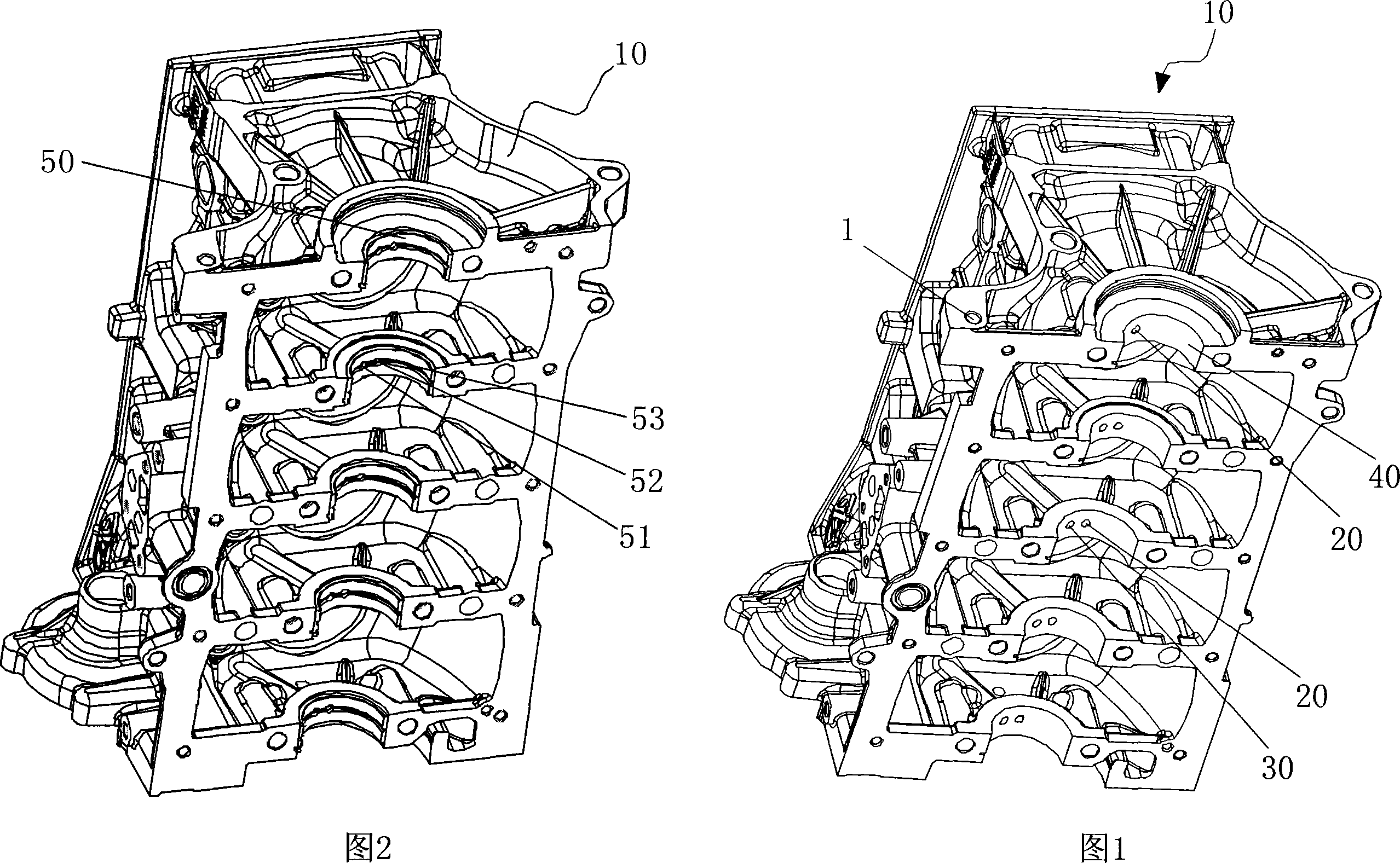
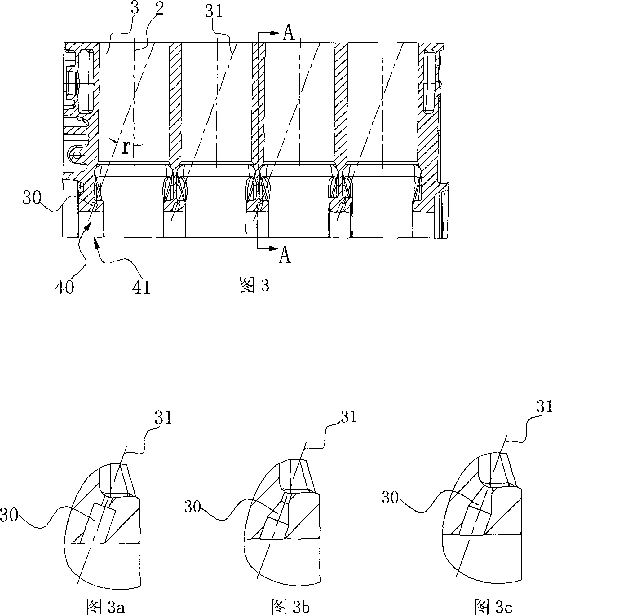
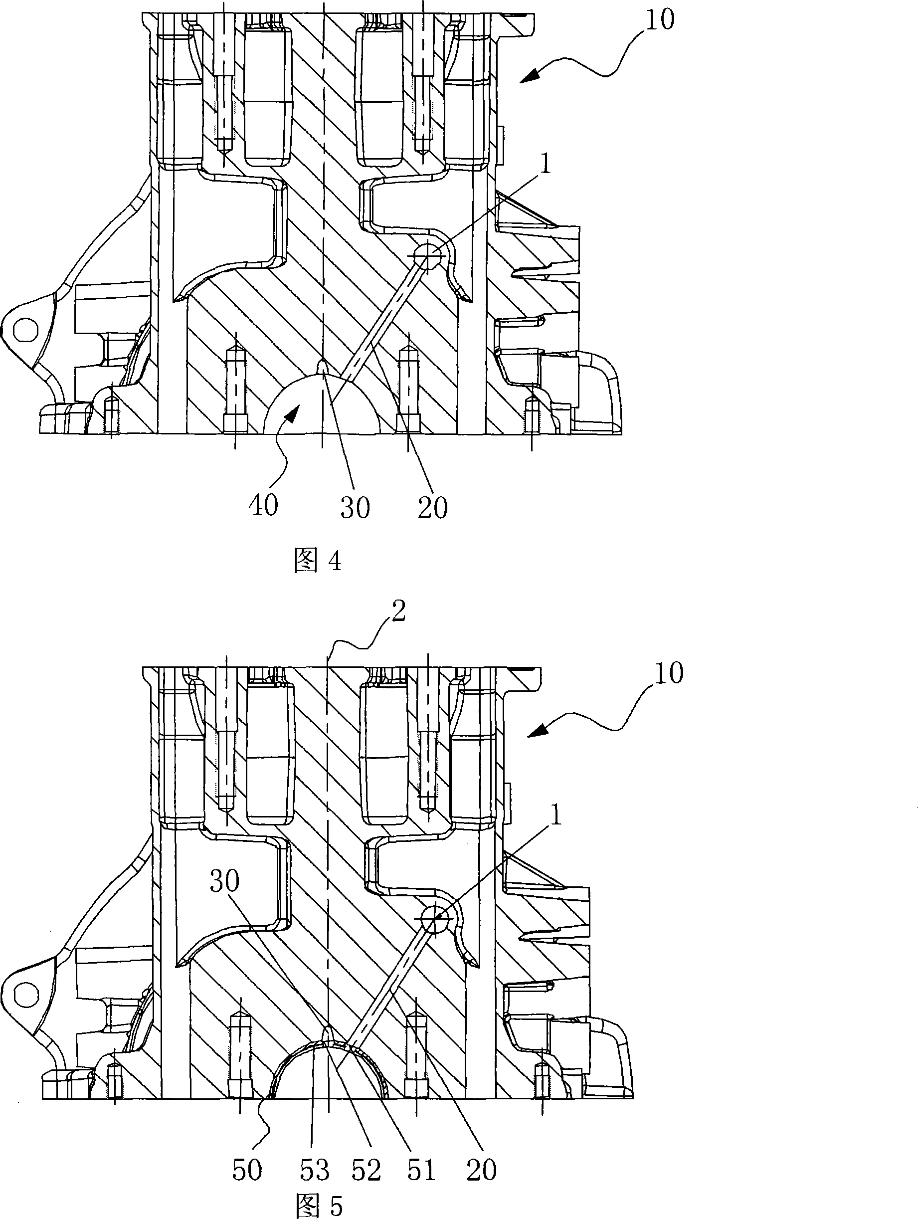
[0013] Figure 1 shows an isometric view of the cylinder block 10. The high-pressure oil pumped by the oil pump first enters the oil passage 4 through the oil passages of other parts, then enters the oil passage 5, enters the oil passage 6 through the oil filter, and then enters The main oil passage 1 penetrates the front and rear ends of the engine. The main oil passage 1 respectively introduces oil into the main bearing lubricating passage 20. The main bearing lubricating passage 20 communicates with the main bearing hole 40, that is, the main bearing lubricating passage 20 extends to the main bearing hole 40 In the hole wall of the main bearing, the main bearing hole 40 on the side of the main bearing lubricating channel 20 is provided with a throttle hole 30, and the main bearing hole 40 is provided with a first hole 51 and a second hole 51 on the wall of the main bearing shell 50. The hole 52 and the oil groove 53 connecting the first hole 51 and the second hole 52, that is, t...


PUM


Abstract

The invention relates to an engine cylinder body lubricant passage. The high pressure oil pumped out of an engine oil pump enters a main oil passage which runs through the front end and the rear end of an engine. The main oil passage respectively guides the engine oil into a main bearing lubricant passage which extends to a hole wall of a main bearing hole; the hole wall of the main bearing hole at the side of the main bearing lubricant passage is provided with an orifice; a main bearing arranged on the main bearing hole is provided with a first hole, a second hole and an oil trough communicated with the first hole and the second hole; the oil trough is arranged in circularity along the working surface of the main bearing; the first hole and the second hole are respectively connected with the main bearing lubricant passage and the orifice; the oil outlet direction of the orifice points at the direction of a piston. By replacing a nozzle of a check valve with the orifice and by adjusting the obliquity of the orifice, the invention causes the oil mouth direction pointing at the direction of the piston to ensure that the lubricant can be sprayed on the piston in order to reach the best lubrication effect.

Description

Technical field [0001] The invention belongs to the field of engine design, and specifically relates to a forced cooling and lubrication of a supercharged engine piston. Background technique [0002] Traditionally, naturally aspirated gasoline engine pistons rely on the lubricating oil splashed up by the crank connecting rod mechanism to fully meet the cooling and lubrication requirements, and no separate forced cooling and lubrication is required. With the development of technology, the engine adopts various advanced technologies to improve engine performance. Among them, supercharging is one of the advanced technologies, which can make the engine lighter, thereby improving the economy of the engine. [0003] The emergence of supercharging technology has greatly increased the engine's power, which has also greatly increased the engine's thermal load. If no measures are taken for the cooling and lubrication of the piston, failures such as cylinder pulling will occur. The piston o...

Claims


Application Information

Patent Timeline
Patent Type & Authority Applications(China)
IPC IPC(8): F01M1/08F01M1/02
CPCF01M2001/066F01P3/08F01M11/02F01M2011/026F01M1/08
Inventor 张育春
Owner CHERY AUTOMOBILE CO LTD
Learn More