Glasses plate and cutting ring for concrete delivery pump

A technology for concrete conveying pumps and cutting rings, which is applied to pumps, pump components, variable capacity pump components, etc. It can solve the problems of increased processing volume, low processing accuracy, and difficulty in ensuring tight extrusion, so as to improve the connection strength, The overall wear resistance is good, and the effect of avoiding direct impact

Inactive Publication Date: 2008-04-09
SANY HEAVY IND CO LTD (CN)
View PDF3 Cites 24 Cited by
  • Summary
  • Abstract
  • Description
  • Claims
  • Application Information

AI Technical Summary

Problems solved by technology

However, this scheme has many basic components and different shapes, which undoubtedly increases the amount of processing, especially for hard alloys, which is difficult to process, so this method actually increases the difficulty of processing and welding of products. Also increased the workload of processing and welding
[0013] (2) Using Z-shaped sheets and fan-shaped plates whose edges are folded lines, although it is possible to make the adjacent fan-shaped plates and adjacent Z-shaped sheets snap together, and by making the butt joints between adjacent plates and sheets become It is bent to improve its airtightness to prevent the concrete mortar from leaking from the joint, but the problem brought by the use of the broken line edge is not only the difficulty of processing, but also the low processing accuracy, and at the same time, affected by the processing accuracy and assembly accuracy, it is actually difficult to ensure end-to-end connection The joint between the fan-shaped plate and the Z-shaped sheet forms a tight extrusion, but it is easy to form a leak point at the joint and cause the seal to fail
[0014] (3) Since the Z-shaped sheet in the discharge hole, the fan-shaped plate on the cutting surface, and the bar-shaped block on the outer ring are independent parts welded to the substrate, and the adjacent Z-shaped sheets, the adjacent fan-shaped The plates are squeezed together to form an occlusal structure and try to make the fold-line splicing gap as small as possible to achieve the sealing effect. The splicing seams between the end-to-end parts are not and cannot be welded, that is, only in the Z-shaped sheet The upper and lower edges and the inner and outer edges of the fan-shaped plate are welded to the substrate, resulting in poor overall performance and low bonding strength with the substrate
In the process of use, the direction of force on the hard alloy plate and sheet at the cutting surface and in the discharge hole is different (the impact force on the fan-shaped plate at the cutting surface is along the width direction of the fan-shaped plate during cutting), and the During the impact, the impact force on the local plates, sheets, and bars is all transmitted to the flux at the welding place, and because the above-mentioned parts are only welded at both ends, it is very easy to cause the hard alloy fan-shaped plate or Z-shaped sheet to fall off, or Due to the impact fracture between the cemented carbide material and the substrate due to missing welding, the entire product will be scrapped, which will reduce its service life

Method used


Image

  • Glasses plate and cutting ring for concrete delivery pump
  • Glasses plate and cutting ring for concrete delivery pump

Examples


Embodiment 1

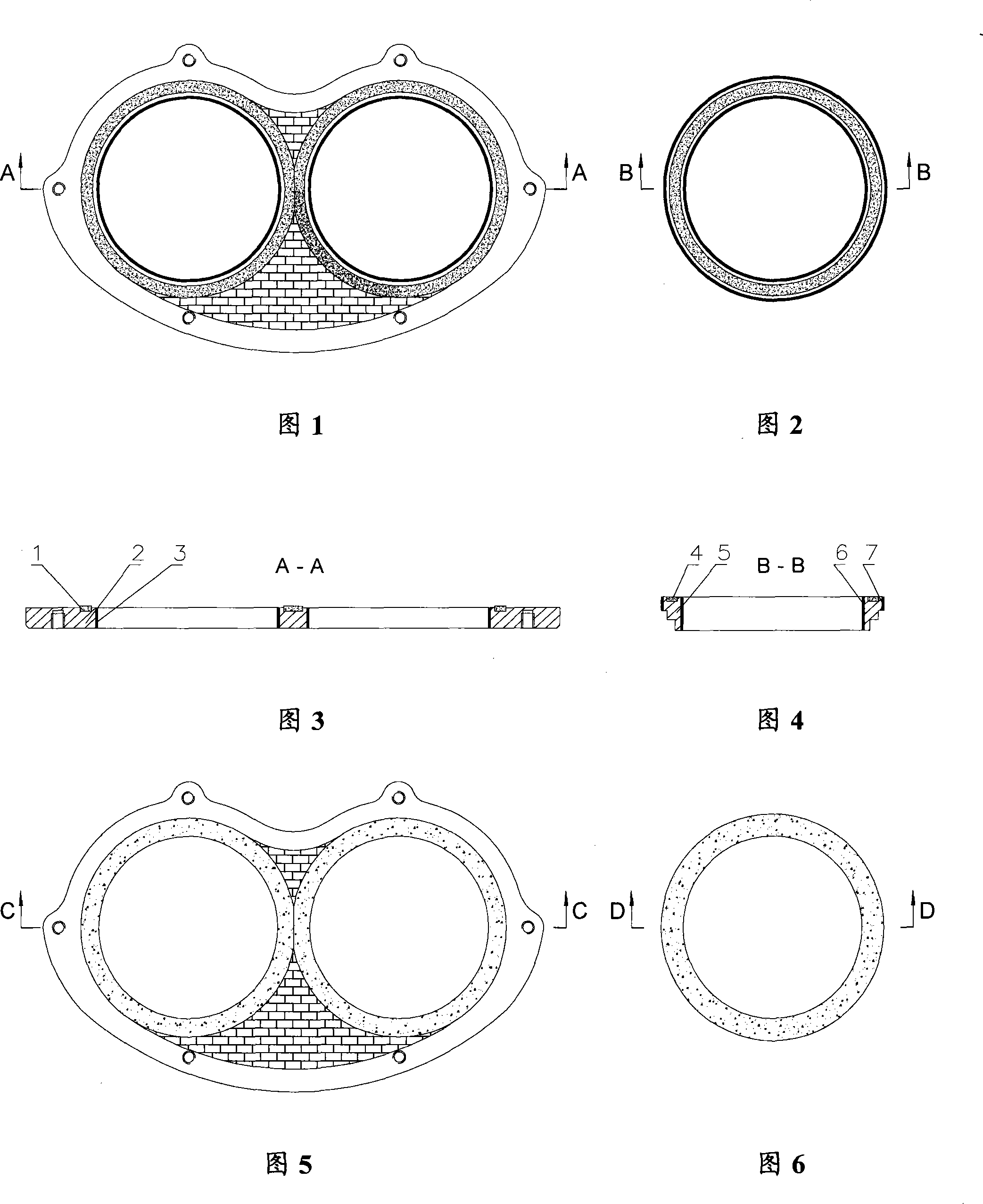
[0043] Embodiment 1 Spectacle plate

[0044] As shown in Fig. 9 and Fig. 11, be the structural representation of cemented carbide spectacle plate of the present invention, comprise spectacle plate substrate 14 and be embedded in the cemented carbide ring that forms substrate wear-resistant plane at substrate cutting surface place, by Fig. 9 can It can be seen that the cemented carbide ring in this embodiment is composed of six cemented carbide blocks 12 in the ring direction.

[0045] As shown in Figure 11, the inner edge of each hard alloy block 12 is turned 90 degrees along the hole wall at the feeding hole of the spectacle plate substrate 14 and extends into the feeding hole to form a hard alloy covering the inner wall of the feeding hole. The ring constitutes the wear-resistant layer on the inner wall of the delivery hole, which improves the wear resistance of the delivery hole and reduces the erosion and wear of the concrete. This kind of cemented carbide block 12 whose ...

Embodiment 2

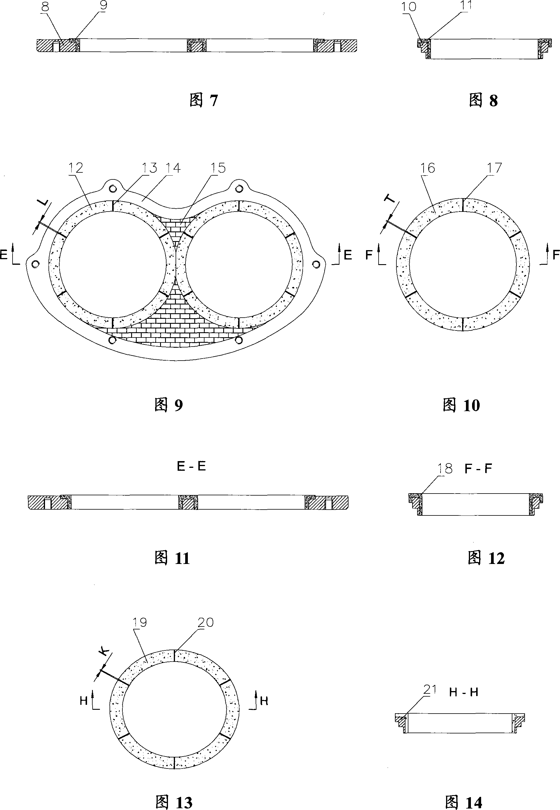
[0052] Example 2 cutting ring

[0053] As shown in Fig. 13 and Fig. 14, it is a cutting ring with an L-shaped cross-sectional carbide ring structure. It includes a cutting ring base body 21 and a hard alloy ring forming a wear-resistant plane of the base body at the cutting surface of the base body. The hard alloy ring is composed of six hard alloy blocks 19 in the ring direction. As shown in FIG. Extending in the feed hole makes the cross section of the cemented carbide block 19 become L-shaped, wherein the arc part is assembled into a cemented carbide ring pasted in the feed hole to form the wear-resistant surface of the feed hole. At the cutting surface and in the feeding hole, a linear gap 20 is formed between adjacent hard alloy blocks, and the entire adjacent surface of the hard alloy block 19 and the cutting ring base 21 is welded together, that is, not only the upper, The lower edge is welded, and the gap 20 formed between the adjacent hard alloy blocks is also fille...


PUM

PropertyMeasurementUnit
widthaaaaaaaaaa

Abstract

The invention discloses glasses plate and a cutting ring used for a concrete delivery pump, comprising a base and a hard alloy ring arranged on the cutting surface of the base; the hard alloy ring radially consists of a plurality of hard alloy blocked; the internal edge of the hard alloy block is folded and extends into a material delivery hole along the internal wall of the material delivery hole which is arranged on the base; a hard alloy cirque attached to the internal wall of the material delivery hole is assembled in the material delivery hole of the base; a linear spacing is reserved between adjacent hard alloy blocks in the material delivery hole at the cutting surface; the hard alloy blocks and the adjacent surfaces of the base are welded together; the linear spacing between adjacent hard alloy blocks are filled with welding flux. The glasses plate and cutting ring has good anti-wear and anti-shock performance and long service life.

Description

technical field [0001] The invention relates to accessories for concrete conveying equipment, in particular spectacle plates and cutting rings for concrete conveying pumps. Background technique [0002] The spectacle plate and the cutting ring are a pair of closely matched and relatively moving parts used on the concrete delivery pump (concrete pump). The cutting ring that swings when pumping concrete plays a cutting role on the concrete. Since concrete passes through the feed hole of the spectacle plate and the cutting ring, the inner wall of the feed hole of the spectacle plate and the cutting ring and the mating surface of the spectacle plate and the cutting ring, that is, the cutting surface, should be treated with wear resistance. [0003] At present, a commonly used cemented carbide spectacle plate has a structure as shown in Figures 1 and 3. A hard alloy ring 1 is embedded in the cutting surface of the spectacle plate substrate 2 by welding to form a wear-resistant pl...

Claims


Application Information

Patent Timeline
Patent Type & Authority Applications(China)
IPC IPC(8): F04B53/00F04B15/02
Inventor 易秀明杨新华李永维
Owner SANY HEAVY IND CO LTD (CN)
Why Eureka
Try Eureka