High-pressure source removing device

A source device and high-voltage technology, applied in the field of high-voltage source device, can solve the problems of occupying space and large amount of construction work.

Inactive Publication Date: 2008-04-09
CHINA HUANQIU CONTRACTING & ENG CO LTD
View PDF0 Cites 4 Cited by
  • Summary
  • Abstract
  • Description
  • Claims
  • Application Information

AI Technical Summary

Problems solved by technology

This adds trouble to on-site construction and quality inspection. If there are multiple inspection points on the same pipeline, it will not only involve a large amount of construction work, but also occupy a lot of space.

Method used


Image

  • High-pressure source removing device
  • High-pressure source removing device

Examples


Embodiment Construction

[0028] The present invention will be further described below in conjunction with accompanying drawing:

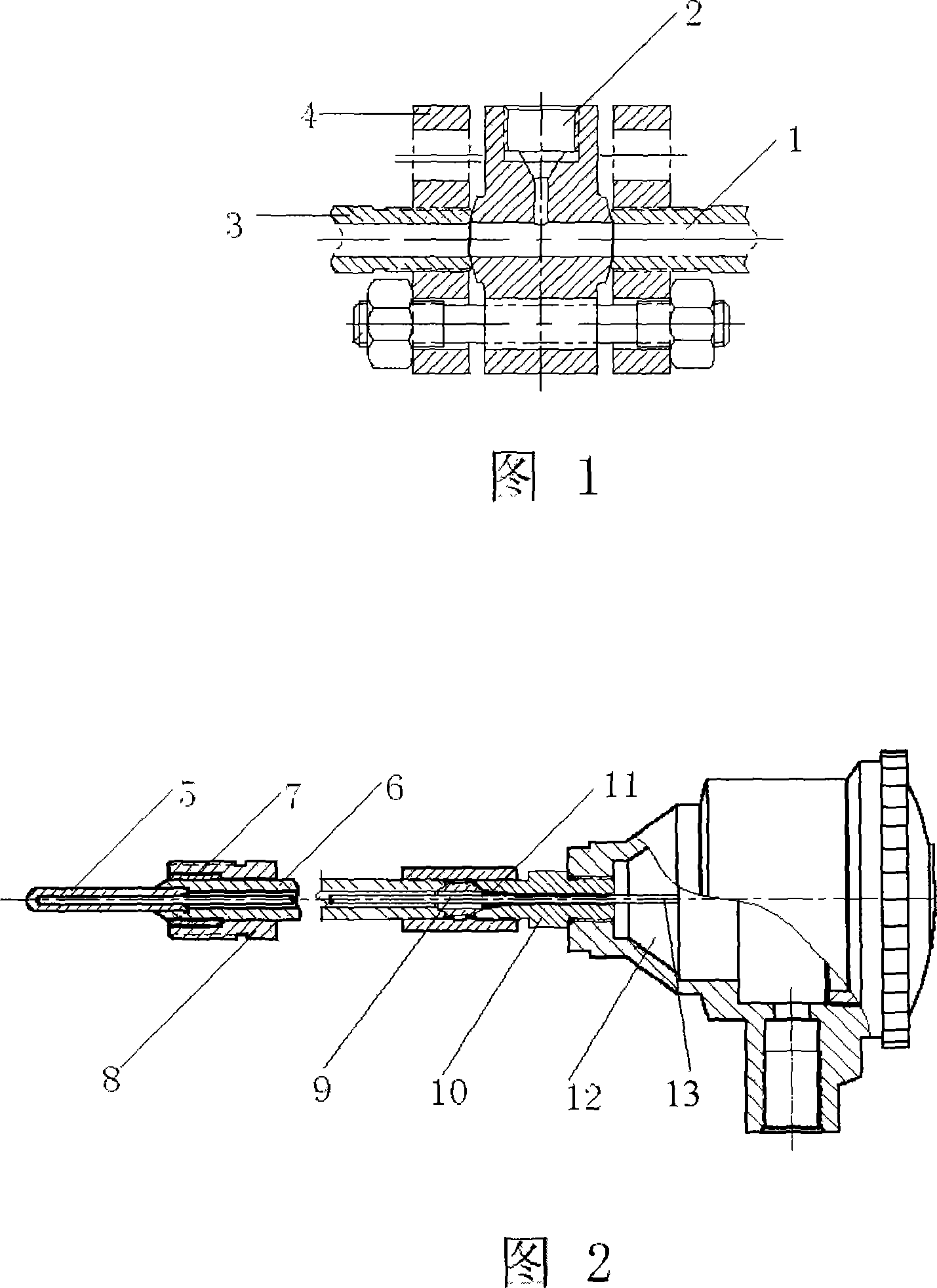
[0029] As shown in Figure 1, the main body of the lens-type high-voltage source component has a through hole 1 matching the pipeline to be detected, and a detection port 2 is opened on the main body, and the detection port communicates with the aforementioned through hole. The detection port can be a variable-diameter port with a large outer diameter and a smaller inner diameter. Multiple detection ports can be set, and can be used as temperature measurement detection ports or pressure measurement detection ports. During installation, the lens-type high-voltage source component is installed between two threaded flanges 4 of the detected high-pressure pipeline 3 .

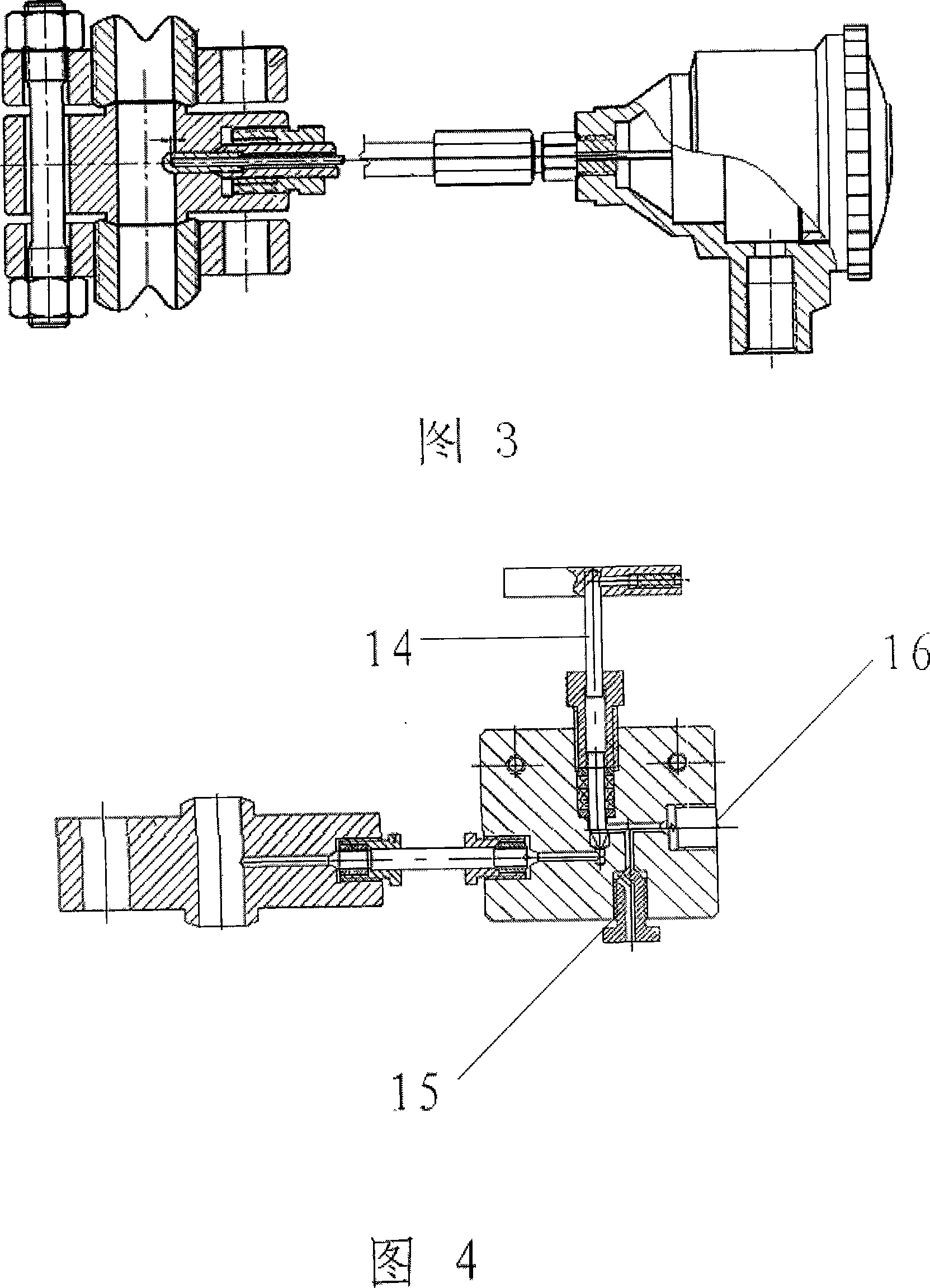
[0030] As shown in Figure 2 and Figure 3, when measuring temperature, a temperature measuring end sleeve 5 and a sleeve 6 are installed in the detection port, and one end of the sleeve is connected to the end sl...


PUM


Abstract

The present invention relates to a high-pressure sourcing device used for simpler test. The technical proposal is that: the high-pressure sourcing device is characterized in that the present invention comprises a lens type high-pressure sourcing component. The component main body is provided with a through hole matching with a testing pipeline. The main body is further provided with a testing opening. The testing opening is communicated with the through hole.

Description

technical field [0001] The invention relates to a high-voltage source extraction device. Background technique [0002] In the production process of petrochemical equipment, such as ammonia synthesis equipment for chemical fertilizers, hydrogenation equipment for oil refining, carbon dioxide supercritical extraction equipment for fine chemicals, and high-pressure boilers for power plants, etc., it is necessary to set temperature and pressure detection points for Monitor the working status of the fluid. In the previous design, the thick-walled protective casing was directly welded to the high-pressure pipeline for temperature measurement, and the high-pressure nozzle was directly welded to the high-pressure pipeline for pressure measurement. This adds trouble to on-site construction and quality inspection. If there are multiple inspection points on the same pipeline, not only the construction volume is large, but also a lot of space is occupied. Contents of the invention ...

Claims


Application Information

Patent Timeline
Patent Type & Authority Applications(China)
IPC IPC(8): F17D3/01G01D21/02G01D11/00
Inventor 王大正张悦昆郑永新程岱
Owner CHINA HUANQIU CONTRACTING & ENG CO LTD
Why Eureka
Try Eureka