Mounting frame for solar cell module

A technology for solar cells and mounting brackets, which is applied in the field of solar cells and can solve problems such as inability to adjust, low output power, and fixation

Inactive Publication Date: 2008-04-09
张文宝
View PDF0 Cites 12 Cited by
  • Summary
  • Abstract
  • Description
  • Claims
  • Application Information

AI Technical Summary

Problems solved by technology

[0003] At present, most of the brackets used to install solar cell modules are welded by angle steel. Since the angle steel is welded, once the welding is completed, the angle is fixed and cannot be adjusted.
When the height of the sun changes and the angle of sunlight irradiated on the solar cell changes, it will affect the absorption efficiency of the solar cell module to the solar light energy
Therefore, the solar battery module adopting the above-mentioned fixed support has a lower output power

Method used


Image

  • Mounting frame for solar cell module
  • Mounting frame for solar cell module

Examples


Embodiment Construction

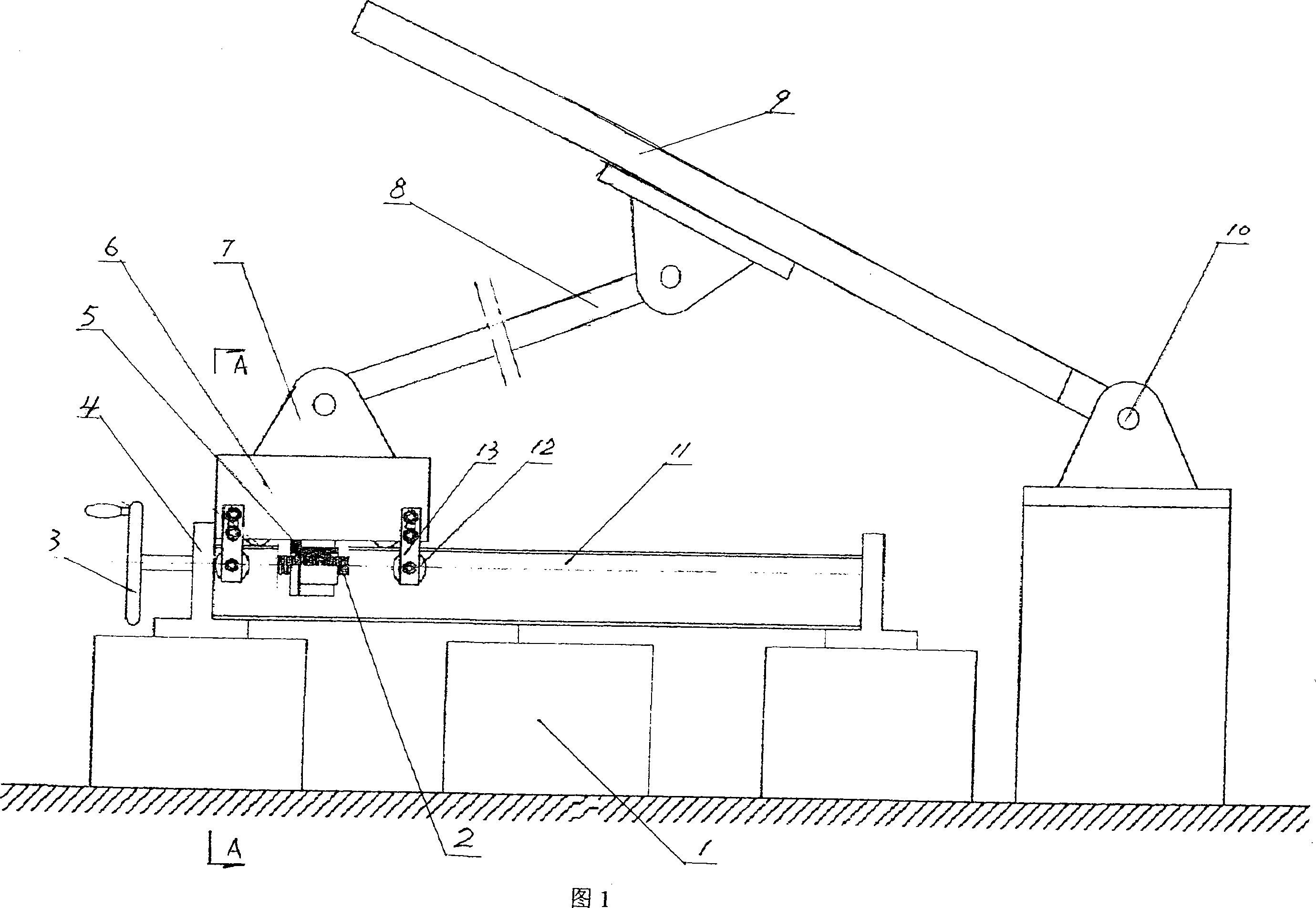
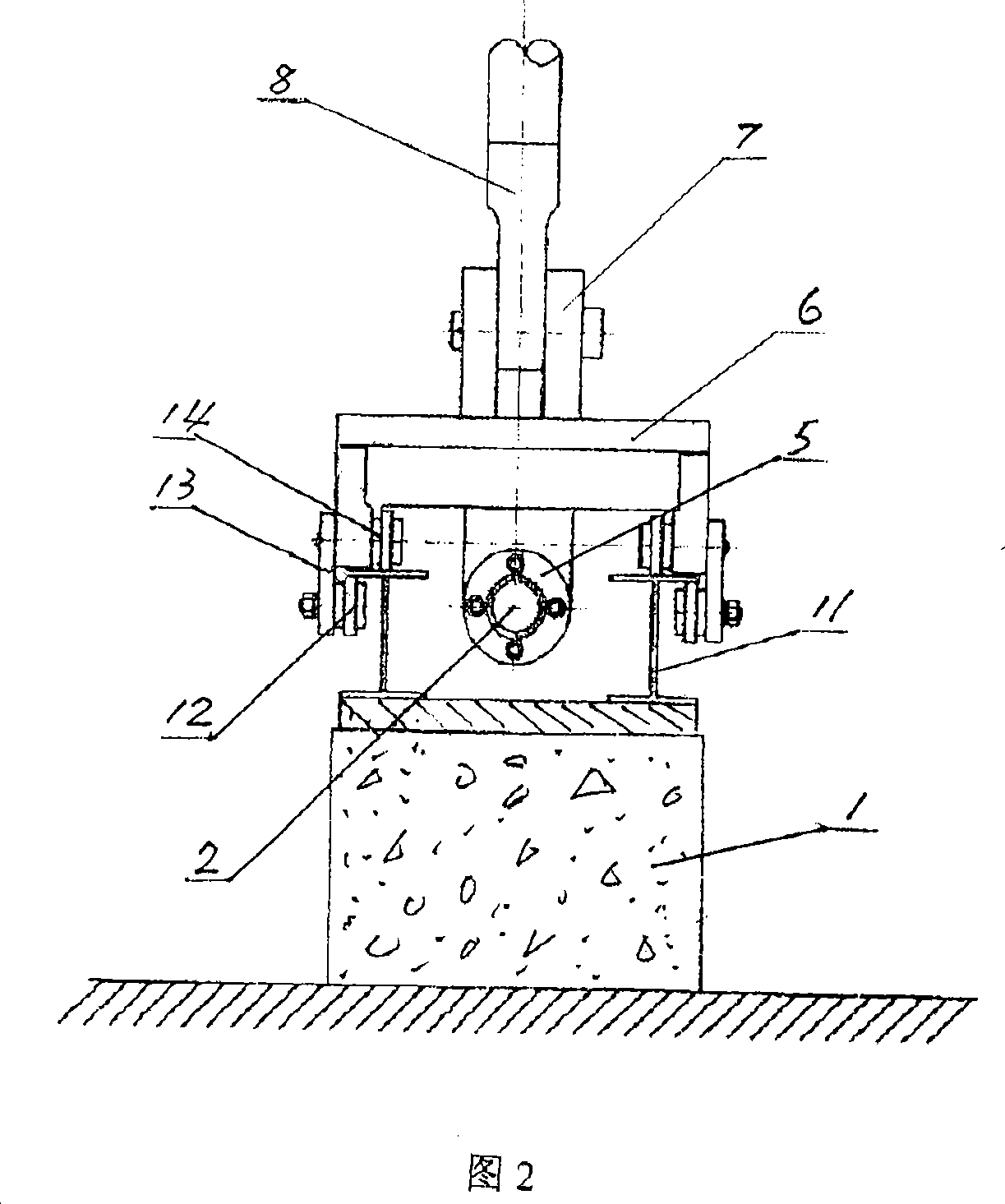
[0012] As shown in FIGS. 1 and 2 , the solar cell module mounting bracket of the present invention includes a base and a solar cell module 9 . Two guide rails 11 are fixed on the base, and the two guide rails are parallel, and bearings 4 are fixed on the base between their same ends. Said support 4 contains a vertical plate, and the horizontal plate formed with it is arranged on the lower side of the vertical plate. The vertical plate surface wherein is perpendicular to the longitudinal direction of guide rail 11, is all processed with through hole on it, and the through hole on two support 4 vertical plates is corresponding. The cross-sections of the two guide rails 11 are I-shaped, and the two side plates of the slide seat 6 are all convex downwards, and an upper roller 14 is installed on the inside of the raised part of the two side plates by means of pin shafts and bearings, and the four upper rollers Arranged symmetrically in a quadrangular shape, they are placed on the ...


PUM


Abstract

The invention discloses an assembly supporting stand for a solar cell component, which comprises a base and solar cell components. The supporting stand is characterized in that the base is provided with two parallel rails, supports are provided between two ends of the rails. A slide seat is arranged on two rails, whose bottom is equipped with quadrangular symmetrical rollers that contacts with the rails, and the slide seat accomplishes movement with utilization of these wheels. The lower surface of the slide seat is provided with a plurality of nuts and a bolt, wherein one end of the bolt passes through two holding bases and nuts between these two bases, and the other end stretches out to connect with a hand wheel. Pin bases are arranged on the slide seat, the lower surface of the solar cell component and the base which is far away from the hand wheel, while the lower edge of the solar cell component is hinged to the pin base which is far away from the hand wheel. The connection rod is arranged between the solar cell component and the slide seat, and two ends of the connection rod are respectively hinged to the pin base of the slider holder and the lower surface of the solar cell component. And utilization of the supporting stand can accomplish higher power output of the solar cell.

Description

technical field [0001] The invention relates to a solar cell. Specifically, it is a mounting bracket for solar cell modules that can adjust the sun's irradiation angle. Background technique [0002] It is well known in the field of solar energy applications that how to maximize the absorption of solar energy by solar cell components and output the maximum power depends on the installation angle of the solar cell components. Theoretically, only when the sunlight is vertically irradiated on the surface of the solar cell can there be maximum power output. [0003] Most of the brackets currently used to install solar cell modules are welded with angle steel. Since the angle steel is welded, once the welding is completed, the angle is fixed and cannot be adjusted. When the altitude of the sun changes and the angle of sunlight irradiated on the solar cell changes, it will affect the absorption efficiency of the solar cell module to the solar light energy. Therefore, the output ...

Claims


Application Information

Patent Timeline
Patent Type & Authority Applications(China)
IPC IPC(8): H02N6/00H02S20/30
CPCY02E10/50
Inventor 张鹏
Owner 张文宝
Why Eureka
Try Eureka