Method, arrangement and valve for controlling rock drilling

A technology of rock drilling and equipment, applied in this field, can solve problems such as function and reliability changes

Inactive Publication Date: 2008-04-09
SANDVIK MINING & CONSTR OY
View PDF0 Cites 7 Cited by
  • Summary
  • Abstract
  • Description
  • Claims
  • Application Information

AI Technical Summary

Problems solved by technology

A problem with known methods is that as drilling conditions and hydraulic fluid properties vary, functionality and reliability vary considerably

Method used


Image

  • Method, arrangement and valve for controlling rock drilling

Examples


Embodiment Construction

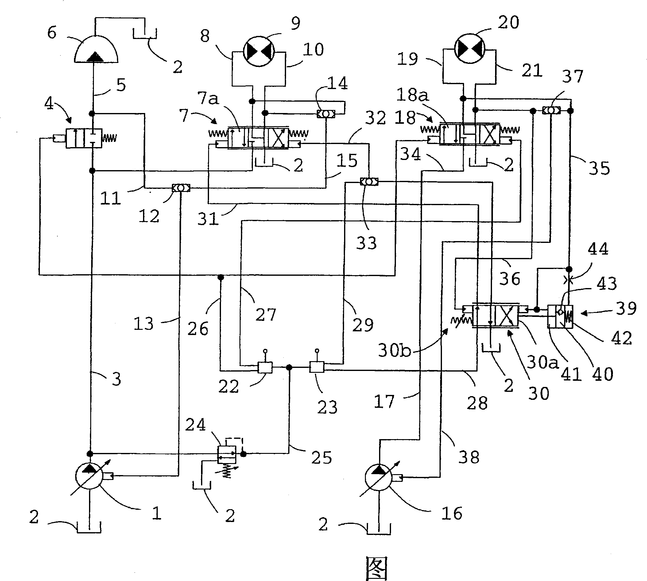
[0008] The drawing shows schematically an embodiment of the invention in the form of a hydraulic diagram. It comprises a first hydraulic fluid pump 1 which is a pressure-controlled volumetric flow pump. Said pump 1 , which supplies hydraulic fluid to the percussion device and the feed motor, draws hydraulic fluid from a hydraulic fluid container 2 . From the pump 1 hydraulic fluid flows along the conduit 3 to the impact control valve 4 and, during impact, the hydraulic fluid further flows via the hydraulic fluid conduit 5 to the impact device 6 . From the percussion device 6 the hydraulic fluid flows back into the hydraulic fluid container 2 . Hydraulic fluid also flows from pump 1 via conduit 3 to feed control valve 7 , from which hydraulic fluid flows via conduit 8 to feed motor 9 of the feed equipment and back via conduit 10 The feed control valve 7 and flows through the feed control valve 7 to the hydraulic fluid container 2 . The feed motor may be a hydraulically opera...


PUM


Abstract

A method, arrangement and valve for controlling rock drilling. In the method, a pressure difference acting across a rotation motor (20) is used to regulate a separate feed regulating valve (30), which, on the basis of this, regulates control pressures of a feed control valve. The arrangement comprises a separate feed regulating valve (30), which, under the influence of the pressure difference acting across the rotation motor (20), regulates control pressures of a feed control valve (7). The valve (30) comprises a separate retarding element (39), which slows down the returning of a spool (30a) of the valve (30) to the normal position, if the spool (30a) has moved away from its normal position under the influence of the pressure difference acting across the rotation motor (20).

Description

technical field [0001] The invention relates to a method for controlling rock drilling, said method comprising the steps of controlling the feed of a rock drilling machine by means of a pressure differential acting on a rotating motor of a drill rod in such a manner that as the rotating an increase in resistance causing the spool of the feed control valve controlling the feed of hydraulic fluid supplied to the feed motor to a position after the pressure differential acting on the feed motor exceeds a predetermined threshold caused by the rotational resistance , at which position the feed motion is converted into a return motion. The invention also relates to a device for controlling rock drilling, said device comprising a rock drilling machine with a percussion device, a rotary motor, a feed motor for propelling the rock drilling machine and a drill connected to the material to be drilled. Rock drilling machine and drill pipe for returning the rock drilling machine; feed cont...

Claims


Application Information

Patent Timeline
Patent Type & Authority Applications(China)
IPC IPC(8): E21B44/06F15B11/16E21B
CPCF15B2211/30525F15B2211/3144F15B11/165F15B2211/6054F15B2211/50572F15B2211/50554F15B2211/7058F15B2211/3127F15B2211/31576F15B2211/329F15B2211/20576F15B2211/6057F15B2211/20546E21B44/06F15B2211/251Y10T137/7837Y10T137/86574F15B11/16
Inventor 韦萨·佩尔托宁
Owner SANDVIK MINING & CONSTR OY
Why Eureka
Try Eureka