Low-temperature flue gas dry desulfurization process for preheating desulfurizer

A low-temperature flue gas and dry desulfurization technology, applied in the field of flue gas desulfurization, can solve the problems of increased energy consumption, low efficiency, and low activity

Inactive Publication Date: 2021-09-07
ANHUI TONGXING ENVIRONMENTAL PROTECTION ENG +1
View PDF11 Cites 2 Cited by
  • Summary
  • Abstract
  • Description
  • Claims
  • Application Information

AI Technical Summary

Problems solved by technology

However, this process requires that the temperature of the flue gas must be guaranteed to be above 170°C to ensure that NaHCO 3 (mainly 600-800 mesh) the activity after decomposition is high enough to fix SO 2 The efficiency is high, otherwise, NaHCO 3 Fine powder (mainly 600-800 mesh) cannot be completely decomposed on the one hand, on the other hand, the activity of the part that can be decomposed is low, and the removal of SO 2 The low efficiency will cause NaHCO 3 waste of
[0004] At present, the engineering application scenarios of the sodium-based dry desulfurization process are limited: it can only deal with high-temperature flue gas, and for low-temperature flue gas, it is often necessary to reburn blast furnace gas to heat the mixed flue gas, so that the desulfurizer can be completely decomposed before it can be used. As a result, the overall energy consumption of the system has increased, the cost of the system has increased, and the economy of the dry desulfurization process has been reduced. Moreover, the heating device cannot make the heating more uniform, and the heating efficiency needs to be improved.

Method used


Image

  • Low-temperature flue gas dry desulfurization process for preheating desulfurizer
  • Low-temperature flue gas dry desulfurization process for preheating desulfurizer
  • Low-temperature flue gas dry desulfurization process for preheating desulfurizer

Examples


Embodiment 1

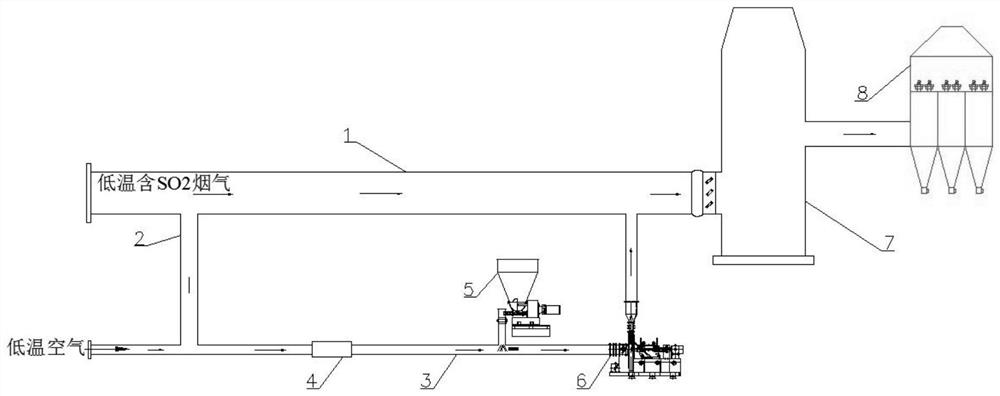
[0055] refer to figure 2 As shown, the low-temperature flue gas dry desulfurization method of preheating the desulfurizer in this embodiment includes the following steps: the flue gas from the coke oven charging coal, coking and dedusting enters the low-temperature flue gas main pipeline 1 through the gas intake point, and flows through the low-temperature flue gas auxiliary pipe 1. The pipeline 2 enters the heating device 4. In this embodiment, the heating device 4 is a gas-gas heat exchange device 41 and an electric heating device 43 for co-heating. , the gas-gas heat exchange device 41 is a steam heat exchanger, through the steam heat exchanger, the temperature of the flue gas from coke charging and dust removal in the coke oven is heated to 130°C, and then enters the electric heating device 43, which is an electric heater , the electric heater heats the temperature of the flue gas from coke oven charging and dedusting to 250°C; then the hot flue gas at 250°C enters the mi...

Embodiment 2

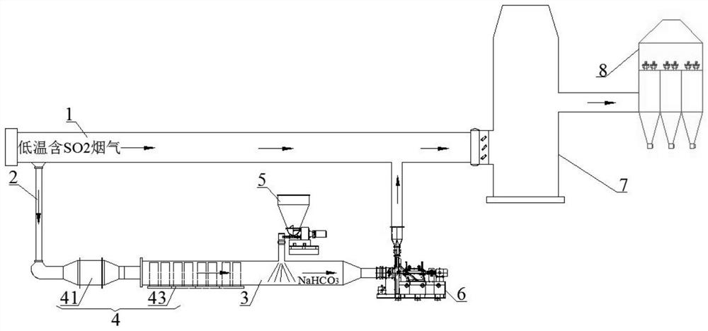
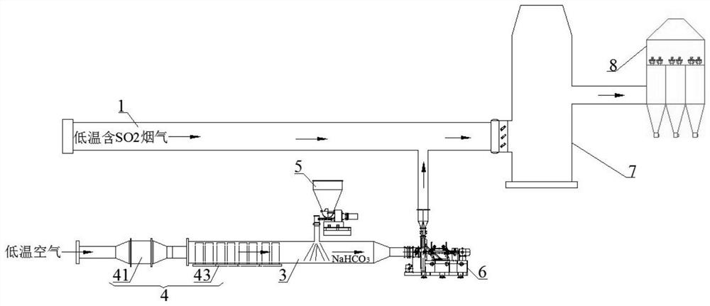
[0057] refer to image 3 As shown, the low-temperature flue gas dry desulfurization method of preheating the desulfurizer in this embodiment includes the following steps: the outdoor low-temperature air enters the gas-gas heat exchange device 41 through the left end of the high-temperature flue gas pipeline 3, and the heating device in this embodiment 4 is air-gas heat exchange device 41 and electric heating device 43 cooperative heating, the outdoor low-temperature air enters the air-gas heat exchange device 41 first, and the gas-gas heat exchange device 41 is a steam heat exchanger, which heats the outdoor air through the steam heat exchanger. The air temperature reaches 130°C, and then enters the electric heating device 43, the electric heating device 43 is an electric heater, and the electric heater heats up the hot air to 250°C; after that, the 250°C hot air enters the middle section of the high-temperature flue gas pipeline 3, which is called 600-800 mesh NaHCO injected ...

Embodiment 3

[0059] refer to Figure 4 As shown, the low-temperature flue gas dry desulfurization method of preheating the desulfurizer in this embodiment includes the following steps. The flue gas auxiliary pipe 2 enters the heating device 4. In this embodiment, the heating device 4 is a hot air heating device 44, and the hot air heating device 44 is a hot blast stove. The combustion medium of the hot blast stove is coke oven gas / blast furnace gas / natural gas, etc.; then the hot flue gas at 250°C enters the middle section of the high-temperature flue gas pipeline 3, and is mixed with the 600-800 mesh NaHCO injected by the weighing feeder 5 3 Fine powder for mixing, pre-decomposing NaHCO 3Fine powder, before the desulfurizer enters the low-temperature flue gas main pipeline 1 and mixes with the coke oven coal charging and dedusting flue gas to activate the activity of the desulfurizer; The main gas pipeline 1 is evenly mixed with the flue gas from coke oven charging and dedusting, and th...


PUM


Abstract

The invention provides a low-temperature flue gas dry desulfurization process for preheating a desulfurizer, and relates to the technical field of flue gas desulfurization. The low-temperature flue gas dry desulfurization method for preheating the desulfurizer comprises the following steps: feeding gas; taking gas; heating: heating the low-temperature gas introduced into a high-temperature flue gas pipeline by a heating device, so that the low-temperature gas is heated to become high-temperature gas; wherein the heating device is a gas-gas heat exchange device, an electric heating device or a hot air heating device; feeding: spraying 600-800-mesh desulfurizer into the middle section part of the high-temperature flue gas pipeline through a weighing feeder, and mixing the desulfurizer with the high-temperature gas; pre-decomposition: mixing high-temperature gas formed by heating with a desulfurizer sprayed into the high-temperature flue gas pipeline, and generating a popcorn type decomposition effect after the desulfurizer reaches a certain temperature; and post-processing. According to the method, NaHCO3 fine powder serving as the desulfurizer is heated in advance to be decomposed, so that the flow of gas needing to be heated is greatly reduced, the energy consumption is reduced, and the efficiency and the applicability and economical efficiency of the process are improved.

Description

technical field [0001] This patent is based on the original application number "202011287153.0" and the name "a kind of preheating desulfurizer containing SO 2 The domestic priority application for the patent of "flue gas dry desulfurization process". The present invention relates to the technical field of flue gas desulfurization, and in particular to the low-temperature flue gas dry desulfurization process of preheating desulfurization agent. Background technique [0002] SO 2 It is the main component of air pollution, composed of SO 2 Acid rain, industrial smog and other problems caused by excessive emissions pose a serious threat to the ecosystem and human health, restricting the development of society. For this reason, the country has issued strict emission standards, and enterprises have also increased investment in flue gas desulfurization treatment. . [0003] Sodium-based dry desulfurization process is based on NaHCO 3 As desulfurizer, NaHCO 3 The fine powder (...

Claims


Application Information

Patent Timeline
Patent Type & Authority Applications(China)
IPC IPC(8): B01D53/83B01D53/50B01D46/02
CPCB01D53/508B01D46/02B01D2258/0283B01D2251/304B01D2259/128B01D2257/302
Inventor 郑勇李朋朋李显宝
Owner ANHUI TONGXING ENVIRONMENTAL PROTECTION ENG
Why Eureka
Try Eureka