Punching machine

A punching machine and mold base technology, applied in the field of punching machine structure, can solve problems such as reducing movement resistance, wasting stamping materials, and complicated manufacturing, and achieve excellent guiding accuracy, high guiding accuracy, and reduced machine weight Effect

Inactive Publication Date: 2008-04-16
嵩亿工业股份有限公司
View PDF0 Cites 0 Cited by
  • Summary
  • Abstract
  • Description
  • Claims
  • Application Information

AI Technical Summary

Problems solved by technology

[0005] 1. The limit slider is used to clamp both sides of the upper mold base, so its volume is relatively large, and it also needs to use more metal materials for forging or casting
[0006] 2. The guiding accuracy of the limit slider to the upper mold base is not only affected by the processing precision of the limit slider and the upper mold base itself, but also affected by the assembly accuracy therebetween. Therefore, the guiding accuracy is often difficult to control, and even the problem of insufficient guiding accuracy and waste of stamping materials often occurs
[0007] 3. There is normal high-speed reciprocating fri

Method used


Image

  • Punching machine
  • Punching machine
  • Punching machine

Examples


Embodiment Construction

[0026] According to the technical means of the present invention, the methods suitable for the implementation of the present invention are listed below, and are described as follows in conjunction with the accompanying drawings:

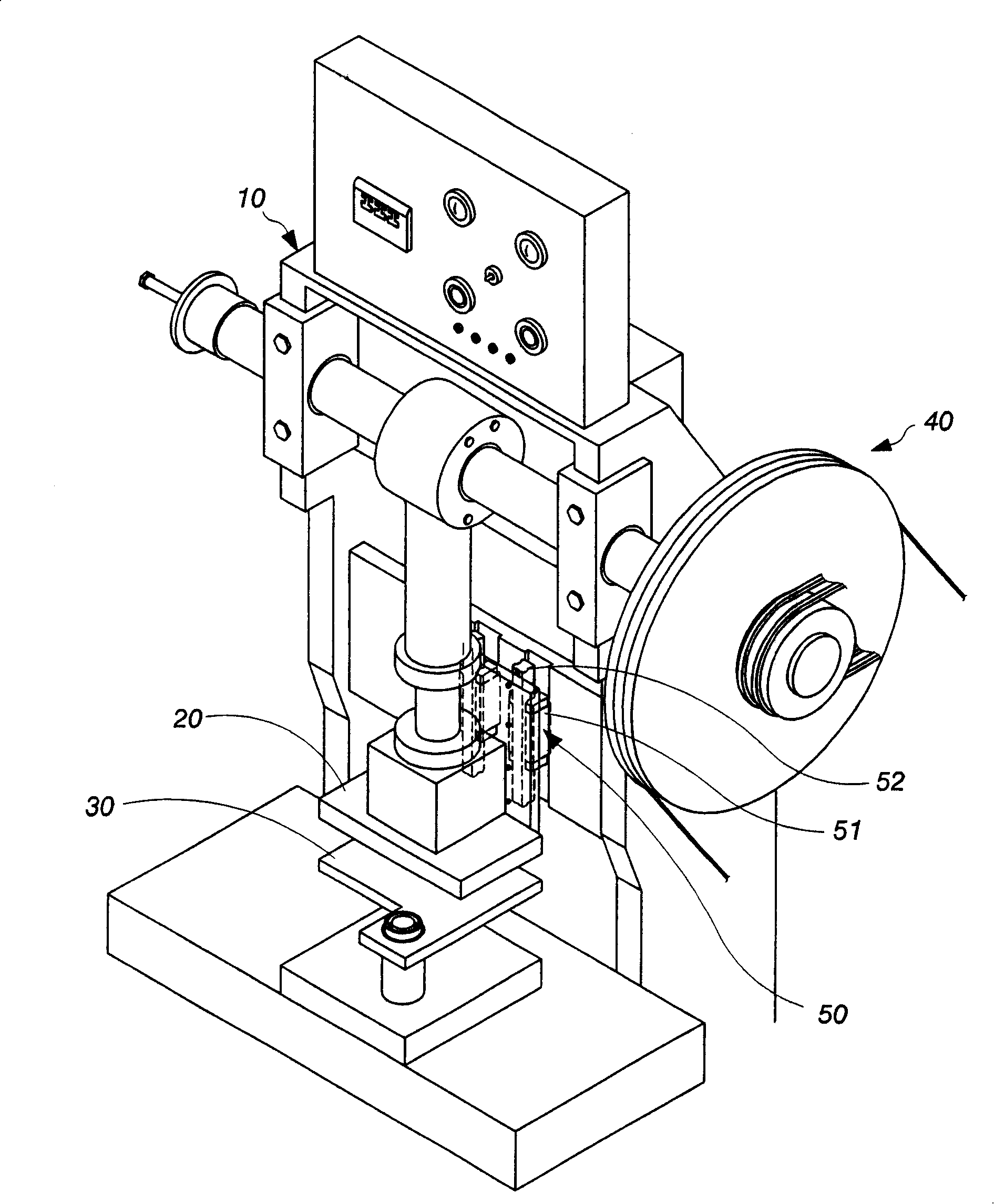
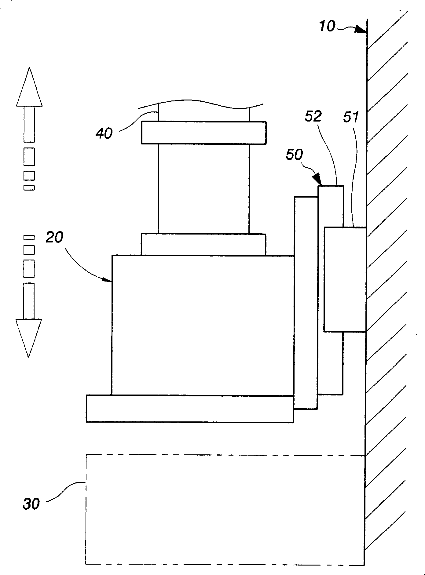
[0027] figure 1 As shown, it is a three-dimensional appearance view of the punch press of the present invention. The composition of the first embodiment of the punch press at least includes a machine platform 10, an upper mold base 20 arranged on the machine platform 10, and a lower mold arranged on the machine platform 10. The base 30, a drive unit 40 for driving the upper mold base 20, and at least one linear slide rail set 50 arranged vertically.

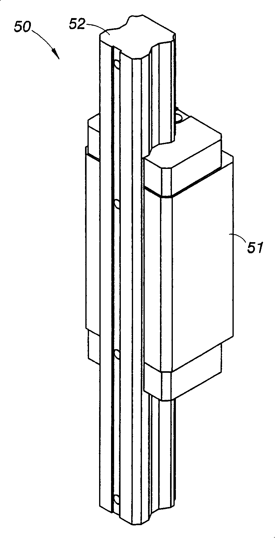
[0028] see figure 1 and figure 2 As shown, among them, figure 2 It is a three-dimensional appearance view of the linear slide rail group of the punch press of the present invention. The linear slide rail group 50 is vertically arranged between the machine table 10 and the upper die base 20. The lin...


PUM


Abstract

The invention provides a punch, at least comprising one machine bench, an upper shoe on the machine bench, a lower shoe on the machine bench, a driving unit for driving the upper shoe, a linear slideway group with at least one vertical furnishings. The upper shoe is subjected to linear guide by linear slideway group to make the operation course of upper shoe more stably quickly and accurately. The setup amount of the linear slideway group can fluctuate as use require and can be set on the rear side or left side or right side, or the linear slideway group can be actualized using setting manner of multi-group and multi-side.

Description

technical field [0001] The invention relates to a structural technology of a processing machine tool, especially a structural technology of a punching machine. Background technique [0002] Generally speaking, the structure of a punch press mainly includes a machine, an upper die set on the machine, a lower die set on the machine, and a drive unit to drive the upper die. . . . [0003] Among them, the upper die base is a vertical reciprocal displacement mechanism used to lift and lower the lower die base in the stamping stroke, so it is necessary to set a limit slider on the machine table relative to the upper die base on both sides of the upper die base. , and the two sides of the upper die base are clamped so that the upper die base is worn between the limit sliders, so that the upper die base can be rubbed against by the limit sliders on both sides during the lifting and stamping stroke And guide to the correct punching direction. [0004] But the guide technology of th...

Claims


Application Information

Patent Timeline
IPC IPC(8): B30B1/00B30B15/04
Inventor 郭礼祥
Owner 嵩亿工业股份有限公司
Why Eureka
Try Eureka