A hot melt binding clamp

A binding clip and hot-melt technology, applied in binding, book binding, adhesives for binding, etc., can solve the problem of difficult page turning, and achieve the effect of easy turning and firm binding

Inactive Publication Date: 2011-04-20
许建成
View PDF0 Cites 1 Cited by
  • Summary
  • Abstract
  • Description
  • Claims
  • Application Information

AI Technical Summary

Problems solved by technology

[0003] There is currently known a hot-melt binding technology, in which a U-shaped hot-melt adhesive is arranged at the bottom of the U-shaped groove, and a cover and a back cover are arranged on the protruding tops of the two sides of the U-shaped hot-melt adhesive on the inner wall of the U-shaped groove , whose thickness is equal to or greater than that of the side of the U-shaped hot-melt adhesive, so that the side page paper will not be blocked on the protruding tops of the two sides of the U-shaped hot-melt adhesive, but the front and back covers of thick materials are fixed On the inside of the hard U-shaped groove, it is very difficult to turn pages

Method used


Image

  • A hot melt binding clamp
  • A hot melt binding clamp
  • A hot melt binding clamp

Examples


Embodiment 1

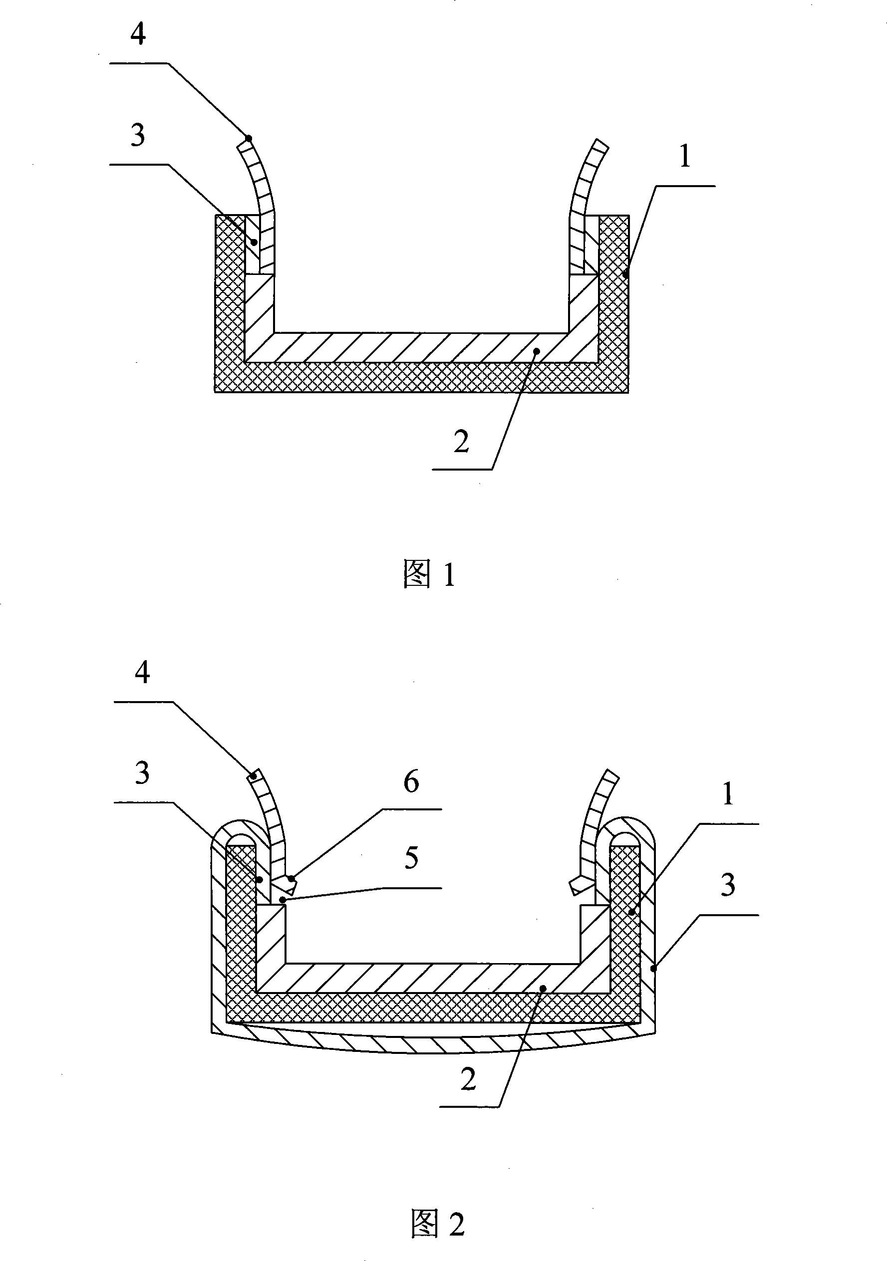
[0029] As shown in Figure 1, a hot-melt binding clip includes a U-shaped groove 1, a U-shaped hot-melt adhesive 2 is provided at the bottom of the U-shaped groove 1, and the two ends of the inner wall of the U-shaped groove 1 are located at U-shaped A thickened layer 3 is arranged on the upper side of the hot melt adhesive 2 , and an active layer 4 is arranged inside the thickened layer 3 . The thickened layer 3 and the active layer 4 are in contact with the sides of the U-shaped hot melt adhesive 2 . The sum of the thicknesses of the thickened layer and the active layer is equal to the thickness of the sides of the U-shaped hot melt adhesive, and the end of the active layer outside the U-shaped groove is connected as a cover or back cover material.

Embodiment 2

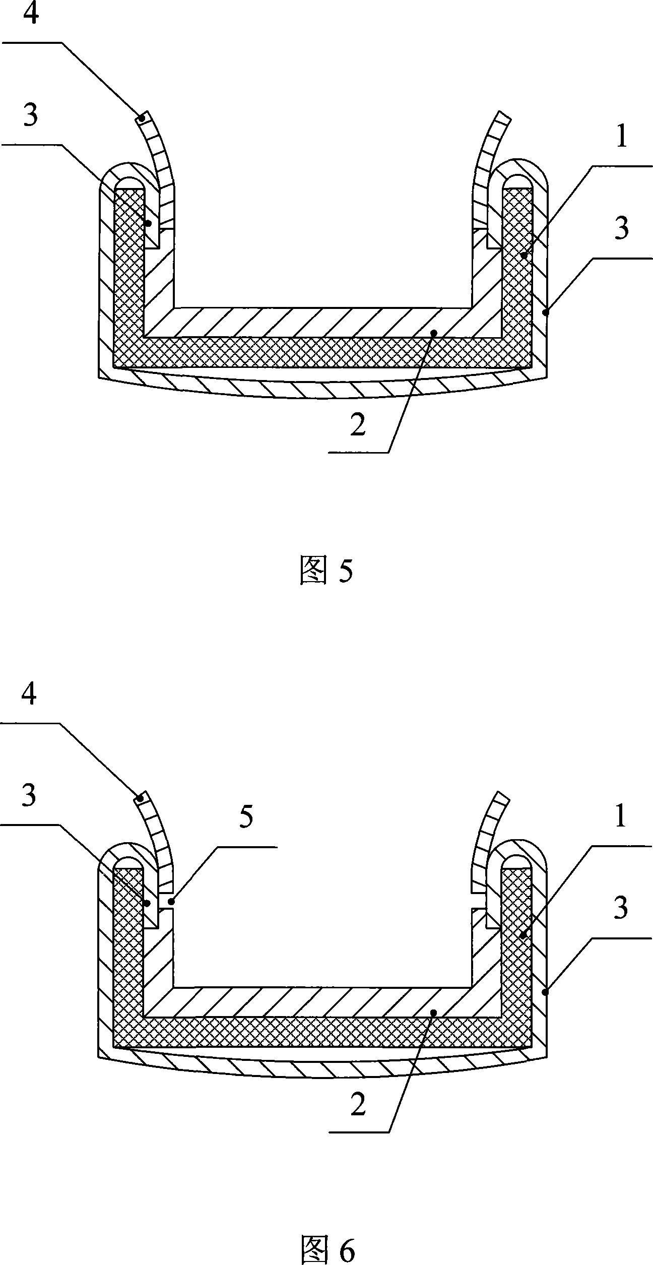
[0031] As shown in Figure 2, a hot-melt binding clip includes a U-shaped groove 1, a U-shaped hot-melt adhesive 2 is provided at the bottom of the U-shaped groove 1, and the two ends of the inner wall of the U-shaped groove 1 are located at U-shaped A thickened layer 3 is arranged on the upper side of the hot melt adhesive 2 , and an active layer 4 is arranged inside the thickened layer 3 . The thickened layer 3 is in contact with the upper side of the U-shaped hot melt adhesive 2, and the end 6 of the active layer located in the U-shaped groove is not in contact with the upper side of the U-shaped hot melt adhesive and forms a gap 5 , the end 6 tilts toward the U-shaped groove. The outside of the U-shaped groove 1 is also provided with a thickened layer 3, the thickened layer 3 on the outside of the U-shaped groove 1 is connected with the thickened layer 3 on the inside of the U-shaped groove 1, and the thickened layer 3 can be As a cover for hot-melt binders. The material ...

Embodiment 3

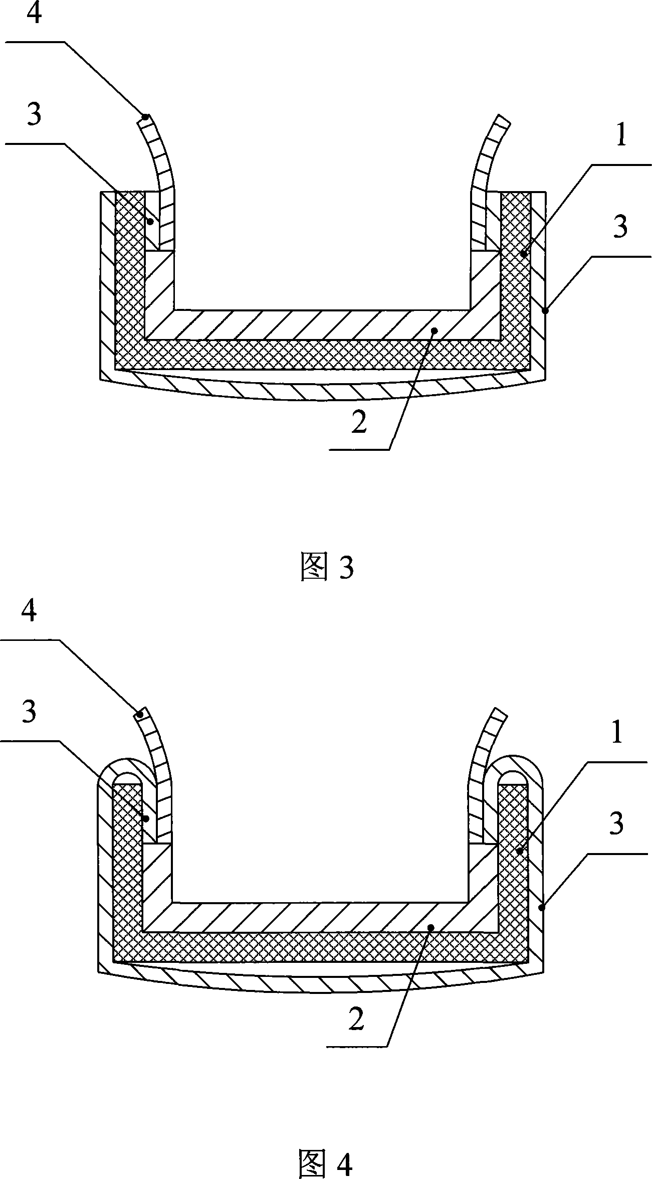
[0033] As shown in Figure 3, a hot-melt binding clip includes a U-shaped groove 1, a U-shaped hot-melt adhesive 2 is provided at the bottom of the U-shaped groove 1, and the two ends of the inner wall of the U-shaped groove 1 are located at U-shaped A thickened layer 3 is arranged on the upper side of the hot melt adhesive 2 , and an active layer 4 is arranged inside the thickened layer 3 . The thickened layer 3 and the active layer 4 are in contact with the upper side of the U-shaped hot melt adhesive 2 . The outer side of the U-shaped groove 1 is also provided with a thickened layer 3, and the thickened layer 3 can be used as the outer skin of the hot-melt binder. The sum of the thicknesses of the thickened layer and the active layer is equal to the thickness of the side of the U-shaped hot melt adhesive, and the end of the active layer outside the U-shaped groove is connected as a cover or back cover material.


PUM


Abstract

The invention relates to a stationers goods, concretely relates to hot-melt bookbinding clamp for bookbinding the document. The said hot-melt bookbinding clamp comprises a U type groove. A U type hot-melt adhesive is in the bottom of the U type groove. A thickening layer is set on the upside of the side of the U type hot-melt adhesive at the two ends of the U type groove. An active layer is set inside the thickening layer. The structure of the said hot-melt bookbinding clamp is reasonable. The invention can make the paper smoothly slip into the U type groove, and being regularly and hard bound to ensure the cover and back cover freely flip over.

Description

technical field [0001] The invention relates to a stationery product, in particular to a heat-melt binding clip used for binding documents. Background technique [0002] Hot-melt binding is a technology that heats and melts preset hot-melt adhesives to glue loose-leaf paper into a booklet. The advantage of this bookbinding technology is convenient, fast. [0003] There is currently known a hot-melt binding technology, in which a U-shaped hot-melt adhesive is arranged at the bottom of the U-shaped groove, and a cover and a back cover are arranged on the protruding tops of the two sides of the U-shaped hot-melt adhesive on the inner wall of the U-shaped groove , whose thickness is equal to or greater than that of the side of the U-shaped hot-melt adhesive, so that the side page paper will not be blocked on the protruding tops of the two sides of the U-shaped hot-melt adhesive, but the front and back covers of thick materials are fixed On the inside of the hard U-shaped groov...

Claims


Application Information

Patent Timeline
Patent Type & Authority Patents(China)
IPC IPC(8): B42C9/00B42B5/00
CPCB42D3/002
Inventor 许建成
Owner 许建成
Why Eureka
Try Eureka