Eureka AIR delivers breakthrough ideas for toughest innovation challenges, trusted by R&D personnel around the world.

Correcting method for quick-speed spin echo pulse sequence and uses thereof

A technology of pulse sequence and spin echo, which is applied in application, medical science, diagnosis, etc., can solve the problem of image quality impact and achieve the effect of solving artifacts

Inactive Publication Date: 2008-04-16
EAST CHINA NORMAL UNIV
View PDF2 Cites 52 Cited by
  • Summary
  • Abstract
  • Description
  • Claims
  • Application Information

AI Technical Summary

Problems solved by technology

[0008] Aiming at the deficiencies of the prior art, the present invention provides a fast spin echo pulse sequence correction method and its application in magnetic resonance imaging technology to solve the problems of artifacts, magnetic field stability and eddy current state imaging in existing FSE images The problem that system factors have an impact on image quality

Method used


Image

  • Correcting method for quick-speed spin echo pulse sequence and uses thereof
  • Correcting method for quick-speed spin echo pulse sequence and uses thereof

Examples


Embodiment 1

[0063] The correction method of the fast spin echo pulse sequence provided by the present invention comprises the following sequential steps:

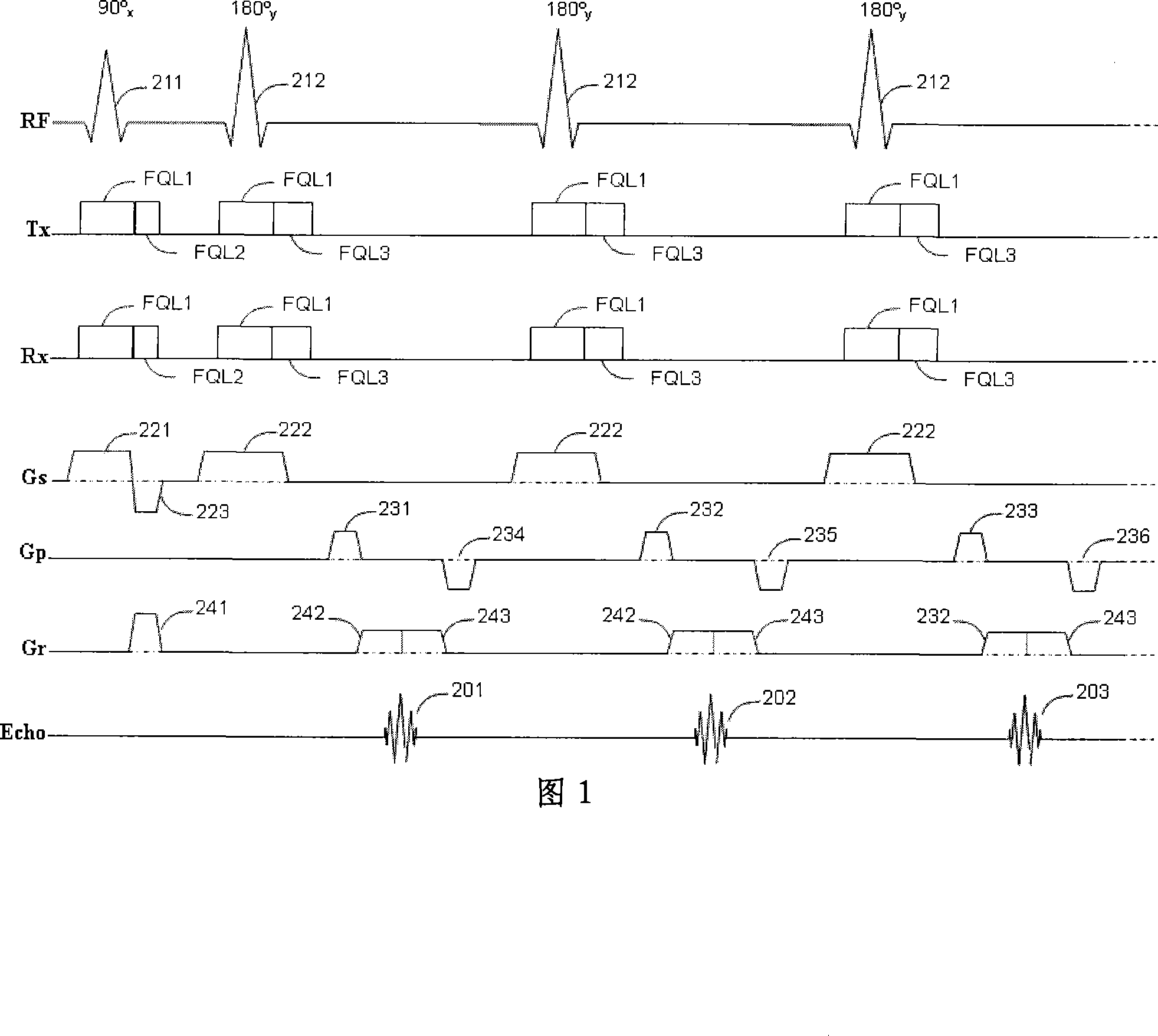
[0064] A. Use the FSE pulse sequence to scan, and correct the amplitude value of the phase gradient pulse in the "reading direction" according to the position of the peak point of the first echo signal in the echo chain;

[0065] B. Use the amplitude value of the corrected dephased gradient pulse to perform FSE pulse sequence scanning, and correct the amplitude value of the read gradient pulse according to the position of the second echo signal peak point in the echo chain;

[0066] C. Use the amplitude value of the corrected dephase gradient pulse and the corrected amplitude value of the read gradient pulse to perform FSE pulse sequence scanning, and correct the phase of the inverted radio frequency pulse according to the phase of all echo signal peak points in the echo chain;

[0067] D. Use the amplitude value of the corrected depha...

Embodiment 2

[0104] The only difference between this embodiment and Embodiment 1 is that the phase correction process of the inverted radio frequency pulse operates in the following order:

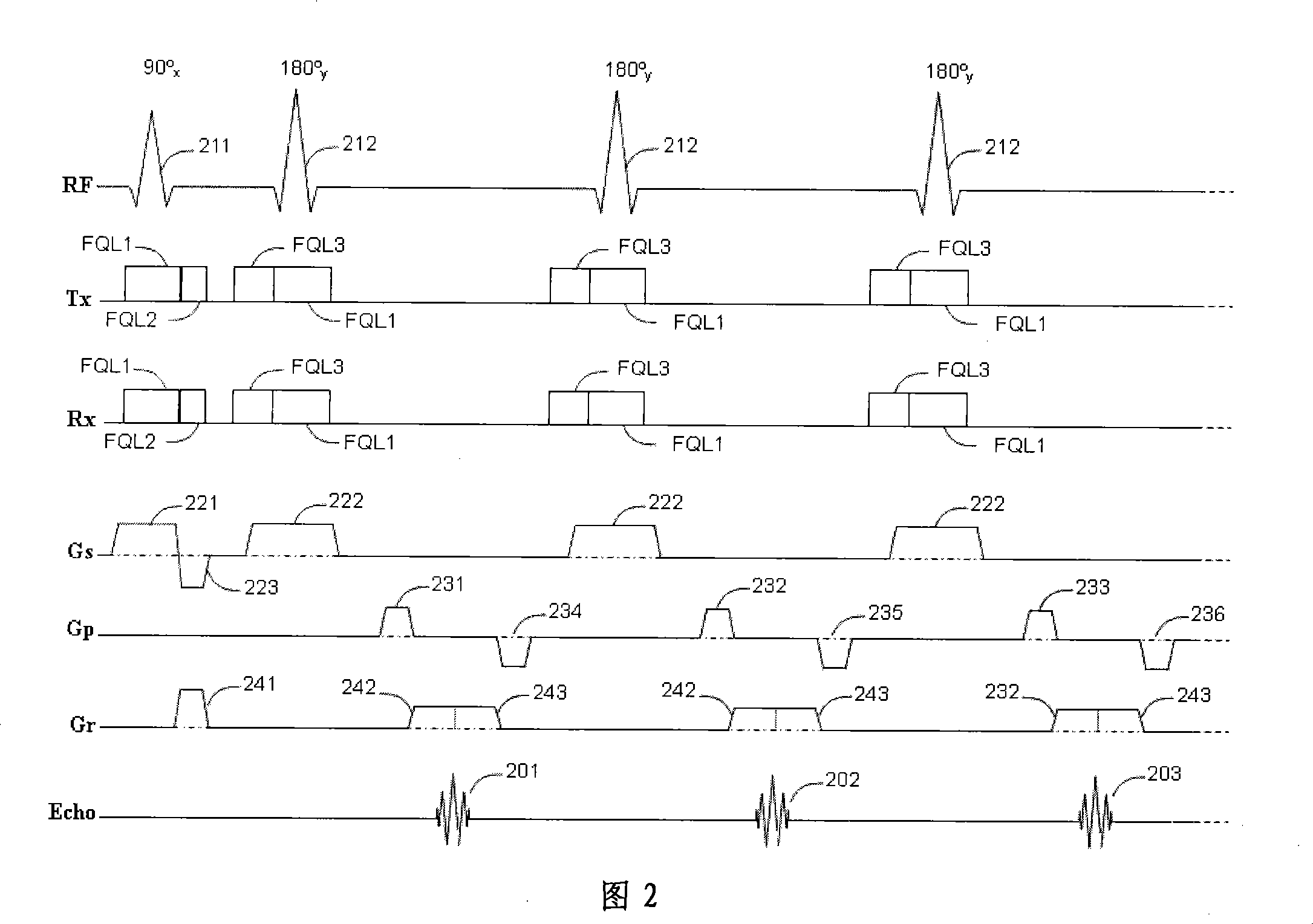
[0105] 1) Execute the FSE pulse sequence shown in FIG. 2 , wherein the amplitude value of the dephasing gradient pulse 241 adopts the corrected GA4, and the amplitude value of the read gradient pulse 243 adopts the corrected GA6. Other sequence parameters are the same as those in Embodiment 1.

[0106] 2) Calculate the standard deviation σ of the peak point phase of the echo (not including the first echo) obtained in this sampling, if σ0 (σ 0 is the preset reference value), then go to step 5, otherwise go to step 3.

[0107] 3) If the frequency offset of the currently selected layer is FQ3, then the new frequency offset FQ3'=FQ3+δ (δ can be 5% of the initial value of FQ3), assign the value of FQ3' to FQ3, and execute again Figure 2 shows the FSE pulse sequence with the updated FQ3.

[0108] 4) Repeat...


PUM


Abstract

The invention provides a method for correcting fast spin echo sequence, aiming at solving the problem that the prior FSE images have the factors of an imaging system such as artifacts, magnetic field stability, eddy current, etc. which have impact on the quality of images. The method can be used to correct the parameter of the fast spin echo (FSE) sequence of a magnetic resonance diagnostic, in particular to correct the parameter of the fast spin echo (FSE) sequence of a magnetic resonance diagnostic which can switch frequence of a transmitter and a receiver. The method for correcting fast spin echo sequence of the invention eliminates the impact of the factors of the imaging system such as artifacts, magnetic field stability, eddy current, etc. on the quality of the images; and as the parameter which is obtained by the correcting method and used in the pre-scanning is the optimal parameter, thereby solving the problem of artifacts of the prior FSE images.

Description

technical field [0001] The invention relates to a correction method of a fast spin echo pulse sequence and an application thereof, belonging to the technical field of magnetic resonance imaging. Background technique [0002] Magnetic resonance imaging (MRI) technology has become a very useful tool in medical diagnosis. Scanning is performed using a conventional magnetic resonance imaging sequence, and a single scan can take several minutes. Such a long scan time not only brings discomfort to the patient, but also greatly degrades the image quality due to artifacts caused by respiration, heartbeat, gastrointestinal peristalsis, and some voluntary movements. The use of fast imaging sequences can shorten the single scan time to a few seconds, thereby reducing image motion artifacts and patient discomfort during scanning. Fast spin echo (FSE) sequence is one of the fast imaging sequences, which has been applied in most MRI systems. Compared with standard spin echo sequences, ...

Claims


Application Information

Patent Timeline
IPC IPC(8): G01R33/561A61B5/055
Inventor 宁瑞鹏李鲠颖
Owner EAST CHINA NORMAL UNIV
Why Eureka
Eureka Blog
Learn More