LCD and backlight module structure, front frame and back board thereof, and manufacturing method thereof

A liquid crystal display and backlight module technology, which is applied in optics, instruments, nonlinear optics, etc., can solve the problems of increasing labor costs and affecting the display quality of backlight modules, and achieve the effects of reducing labor costs, saving assembly time, and good assembly

Active Publication Date: 2008-04-16
AU OPTRONICS CORP
View PDF0 Cites 27 Cited by
  • Summary
  • Abstract
  • Description
  • Claims
  • Application Information

AI Technical Summary

Problems solved by technology

The currently used backplane 135 will attach a layer of protective film 1352 on the board body 1351, as shown in Figure 2b, the protective film 1352 can prevent the backlight module from rubbing against the metal plate body 1351 during the assembly process to generate some debris , which affects the display quality of the backlight module
Since the currently used protective film 1352 is attached manually, in the process of attaching, due to the large area of ​​attachment, it takes a considerable amount of time for the operator to attach it, which increases a lot of labor costs

Method used


Image

  • LCD and backlight module structure, front frame and back board thereof, and manufacturing method thereof
  • LCD and backlight module structure, front frame and back board thereof, and manufacturing method thereof
  • LCD and backlight module structure, front frame and back board thereof, and manufacturing method thereof

Examples


Embodiment Construction

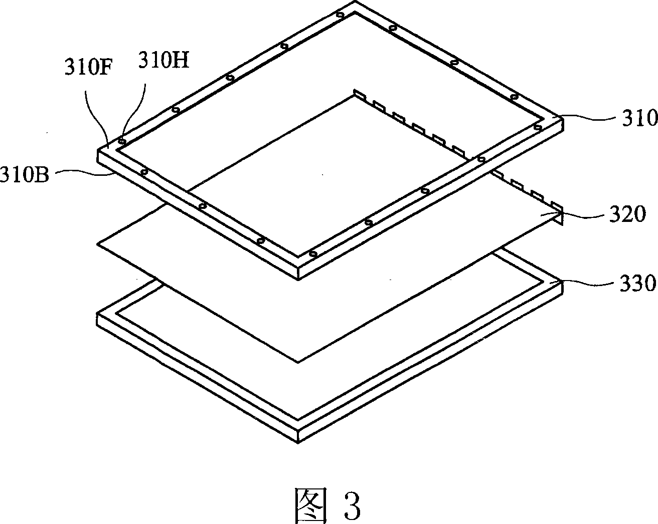
[0096] FIG. 3 is a schematic structural diagram of an embodiment of the liquid crystal display of the present invention. 3, the liquid crystal display of the present invention includes a front frame 310, a liquid crystal panel module 320, and a backlight module 330. The front frame 310 has a front surface 310F, a rear surface 310B, and at least one hole 310H, and a rear surface 310B of the front frame 310 It contacts with the liquid crystal panel module 320 and connects and fixes the liquid crystal panel module 320 and the backlight module 330. 4a and 4b are schematic bottom views of the front frame structure in the present invention. As shown in FIG. 4a, the front frame 310 includes a frame body 311 and a cushioning material 312. The frame body 311 includes a plurality of side edges 313 and a plurality of corners 314. The corners 314 are connected to the intersection of the equal sides 313, and the cushioning material 312 is attached to at least one side 313 of the rear surface 3...


PUM


Abstract

The invention discloses a liquid crystal display and its backlight module structure, front frame, back plate and a method for manufacturing the same. The liquid crystal display comprises a backlight module, a liquid crystal panel module arranged in front of the backlight module, and a front frame comprising a frame body and a fender. The frame body is provided with a hole, and the fender comprises a first part and a second part, wherein, the first part is arranged in the hole for connecting and fixing the liquid crystal panel module and the backlight module through the front frame, while the second part is arranged between the frame body and the liquid crystal panel module. The method of manufacturing the liquid crystal display is as follows: the fender is formed on the front frame through ejecting and shaping; the liquid crystal panel module and the backlight module are connected and fixed through the front frame; the fender is clamped between the front frame and the liquid crystal panel module.

Description

Technical field [0001] The invention relates to a liquid crystal display, in particular to a backlight module structure, a front frame, a back plate and a manufacturing method of the liquid crystal display. Background technique [0002] Regarding the general prior art liquid crystal display structure as shown in FIG. 1a, it mainly includes a front frame 110, a liquid crystal panel module 120 and a backlight module 130, wherein the front frame 110 is used to connect and fix the liquid crystal panel module 120 and the backlight module 130. The front frame 110 often uses a soft rubber material 111 (shading strip) attached to the front surface as a buffer material 111 (shading strip) between the frame 112 of the front frame 110 and the liquid crystal panel module 120, as shown in FIGS. 1b and 1c. FIG. 1b is a top view of the front frame 110. FIG. 1c is a bottom view of the front frame 110. Since the currently used buffer material 111 (shading strip) is mostly laminated by double-side...

Claims


Application Information

Patent Timeline
Patent Type & Authority Applications(China)
IPC IPC(8): G02F1/13357G02F1/1333F21V21/00G02F1/1335
Inventor 陈志嘉陈建元
Owner AU OPTRONICS CORP
Why Eureka
Try Eureka