Blow molding forming bottle with handle and manufacturing device for the same

A technology of blow molding and manufacturing devices, which is applied to container handles, bottles, and other household appliances, etc., and can solve the problems of troublesome removal of the support plate 108 and the easy removal of the handle 104

Active Publication Date: 2008-04-23
FRONTIER CORP
View PDF0 Cites 11 Cited by
  • Summary
  • Abstract
  • Description
  • Claims
  • Application Information

AI Technical Summary

Problems solved by technology

[0012] However, in the case of installing the support plate 108, although it is effective to prevent the handle 104 from coming out, when the use of the bottle is over and the bottle body 100 is separated from the handle 104, it is very troublesome to detach the support plate 108, which becomes a problem when separating. obstacle
[0013] In addition, in order to make the mounting state of the bottle body 100 and the handle 104 firm, it is conceivable to form the bottom side recesses 102, 103 deeper, or to shape the bottom side

Method used


Image

  • Blow molding forming bottle with handle and manufacturing device for the same
  • Blow molding forming bottle with handle and manufacturing device for the same
  • Blow molding forming bottle with handle and manufacturing device for the same

Examples


Embodiment 1

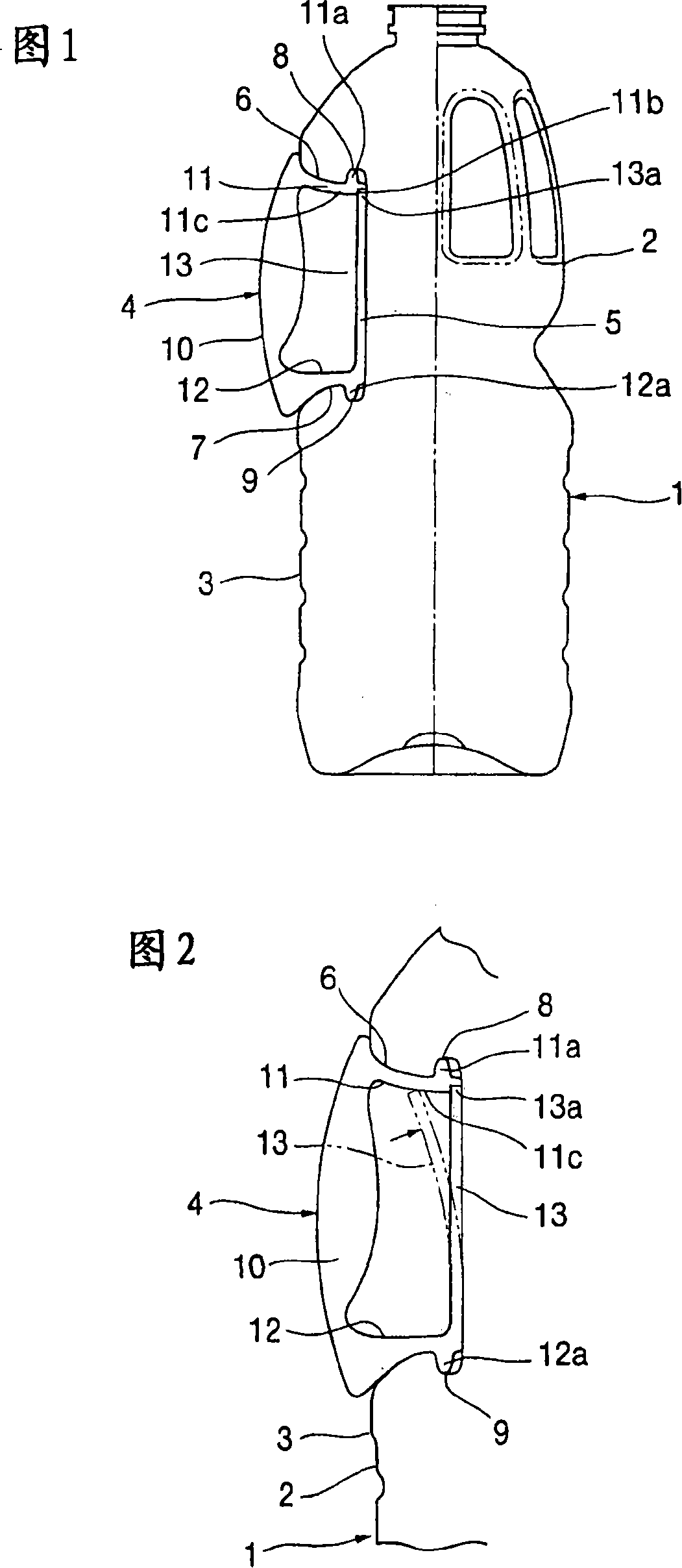
[0038] The present embodiment 1 is a bottle with a handle corresponding to the invention of technical scheme 1. The bottle 1 is a bottle made of polyester resin formed by blow molding, and a handle 4 made of the same polyester is attached to the surface of the trunk portion 3 of the bottle body 2 later.

[0039] The bottle 1 with handle 4 is described in more detail below. In order to install the handle on the surface of the body part 3 of the bottle body 2, a part of the circumference is cut off to form the handle mounting part 5 at a position recessed from the circumference. The opposite positions form bottom-side recesses 8, 9 consisting of pits of predetermined depth and shape.

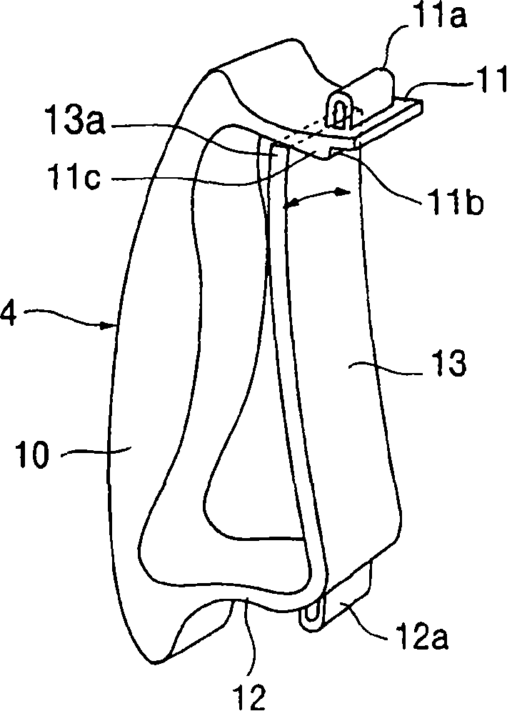
[0040] In handlebar 4 as image 3 As shown, the handle portion 10, the upper arm 11 and the lower arm 12 protruding from the handle portion 10 in the horizontal direction, and the upper and lower bottom side recesses 8, 9 respectively formed on the outside of the front ends of the upper and lower...

Embodiment 2

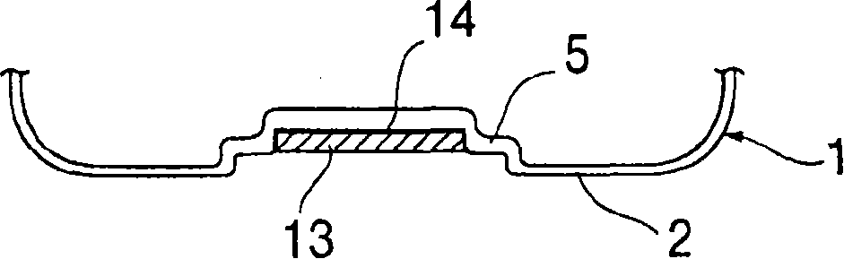
[0044]This embodiment 2 corresponds to the invention described in technical solution 2, such as Figure 4 As shown, on the front of the mounting part 5 corresponding to the support plate 13, a recess 14 is formed to accommodate the support plate 13, and the support plate 13 is accommodated in the recess 14, thereby preventing the support plate 13 from shaking to the left and right and causing the support Power is unstable.

Embodiment 3

[0046] This embodiment 3 corresponds to the invention described in technical solution 3, on the slope 11c formed under the upper arm 11 of the handle 4 as Figure 5 The guide rib 15 is formed as shown, and the upper end portion 13a of the support plate 13 is formed with the notch portion 13b engaged with the guide rib 15, as shown by the arrow from the position of the dashed line 1 in FIG. When the support plate 13 is pressed in by joining 11b, the upper end portion 13a of the support plate 13 is guided without swinging left and right, and the support plate 13 can be joined to a predetermined position in a correct posture.


PUM


Abstract

The present invention relates to a blow-moulding formed bottle with handle and its production equipment. The mounting strength of said handle is raised, and sand handle is not easily separated from bottle body. It is characterized by that in the blow-moulding forming process two cylinders are respectively set, said two cylinders can be used for driving two cams, and said two cams can be used for forming upper and lower bottom side dishes, so that the action of the lower cam side is front and the action of the upper cam side is late, the dish depth and form of lower bottom side dish are identical to that of upper bottom side dish, the combination portions of said handle can be firmly combined in the above-mentioned upper and lower bottom side dishes, therefore the mounting strength of said handle can be raised, and said handle can not be easily separated from said bottle body.

Description

[0001] This application is a divisional application of the invention patent application submitted by Kaikai Co., Ltd. and Airtech ALT Co., Ltd., with the application number "200410045896.1" and the filing date of "May 25, 2004". technical field [0002] The present invention relates to a blow-molded bottle with a handle and a manufacturing device for the bottle. A bottom recess for attaching a handle is formed on the surface of the body portion, and a handle that is separately formed later is attached to the bottom recess. Background technique [0003] Blow-molded bottles are often used as liquid containers such as beverages represented by mineral water, edible fats and oils, and seasoning liquids. When such a bottle is more than 250ml and less than 1800ml, there are many examples where no handle is usually provided. However, when it is more than 1800ml, it is inconvenient to use if there is no handle, so there are many bottles with handles. [0004] In this bottle with a ...

Claims


Application Information

Patent Timeline
IPC IPC(8): B29C49/30B65D1/02B65D23/10
CPCB29L2031/7158B29L2031/463B29C49/06B29C49/12B29C49/4802B29C49/54B29C49/541B29C2049/4807B29C2049/4889B29C2949/0715
Inventor 折元宏行
Owner FRONTIER CORP
Why Eureka
Try Eureka