

Compression type packer
A compression packer and seat sealing technology is applied in the field of packers for sealing off various oil layers or tubing casings in oil and gas wells. Convenient, sensitive unlocking action, reducing the effect of construction accidents
- Summary
- Abstract
- Description
- Claims
- Application Information
AI Technical Summary
Problems solved by technology
Method used
Image

Examples
Embodiment 1
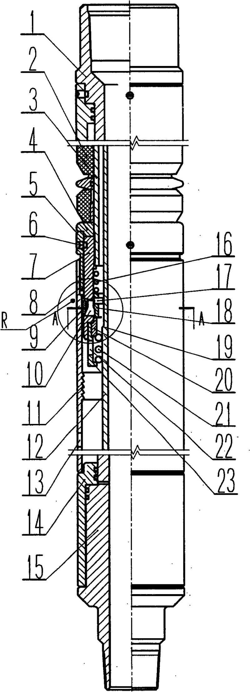
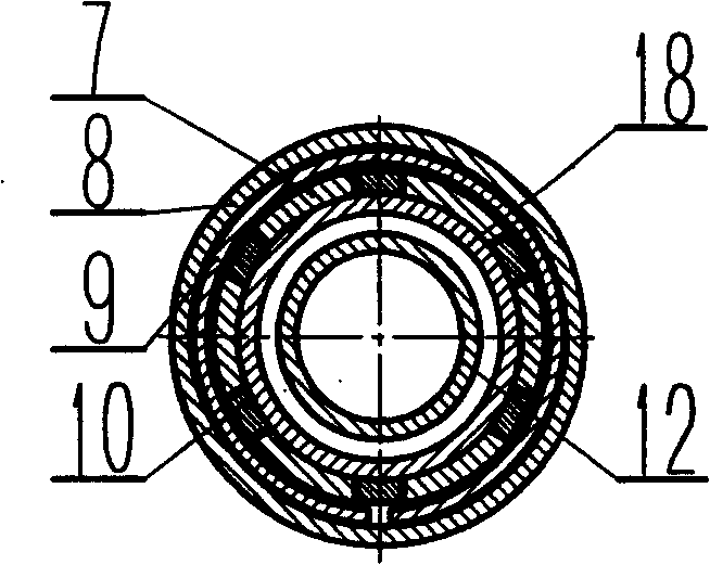
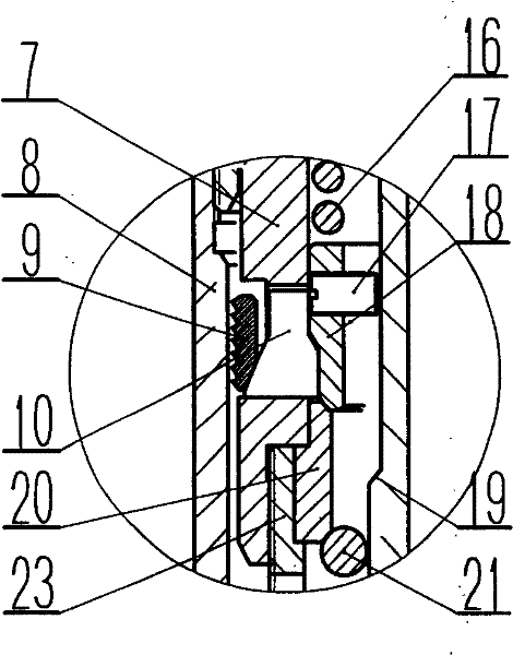
[0025] Such as Figures 1 to 3 As shown, the compression packer includes an upper joint 1 , a well flushing mechanism, a rubber cartridge sealing mechanism, a seat sealing mechanism and a lower joint 15 . The seat seal mechanism includes a lock sleeve 8, a lock ring 9, a wedge-shaped lock block 10, a lock ring seat 7, and a central tube 12. The outer cylindrical surface of the lower end of the lock ring seat 7 is provided with an annular groove, and the lock ring 9 is installed in the annular groove. The groove is provided with several waist holes communicating with the inner side, each waist hole is equipped with a lock block 10, the lock ring 9 is a split ring, and the outer peripheral surface of the lock ring 9 is provided with one-way locking ring teeth. The sleeve 8 is provided with an annular tooth 11 that cooperates with the annular tooth of the lock ring 9. The lower end of the lock ring 9 is provided with an inner conical surface at the contact part with the lower end...
Embodiment 2
[0031] Another solution of the present invention is as Figures 6 to 8 As shown, the same parts as those in Embodiment 1 will not be described here again. There is an annular boss 28 on the central tube 12 that matches the inner wall of the lock block 10 . The lower end of the boss 28 is provided with two upper and lower steps 25 and 26 that cooperate with the step 24 at the middle part of the inner side of the lock block 10 . Before and after the seat seal, the upper step 25 at the lower end of the boss 28 cooperates with the step 24 on the lock block 10, see Figure 8 and Figure 9 . When unsealing, lift the central tube, the lower step 26 at the lower end of the boss 28 cooperates with the step 24 on the lock block 10, see Figure 10 At this time, the lower end of the step 24 of the lock block is embedded in the annular groove 27 at the lower end of the central tube boss 28, the lock sleeve 8 compresses the lock ring 9 and shrinks to make the lock block 10 move radially ...
PUM
 Abstract
Description
Claims
Application Information