Wind exchange radiator

A radiator and fan technology, applied in the direction of heat exchanger type, indirect heat exchanger, lighting and heating equipment, etc., can solve the problem of poor heat exchange effect of heating radiator

Inactive Publication Date: 2008-04-23
秦子建
View PDF0 Cites 0 Cited by
  • Summary
  • Abstract
  • Description
  • Claims
  • Application Information

AI Technical Summary

Problems solved by technology

[0003] The present invention aims to solve the technical problem of poor heat exchange effect of existing heating radiators, provide an air exchange radiator with high heat exchange efficiency, and further provide an air exchange radiator that can convert and utilize different heat sources

Method used


Image

  • Wind exchange radiator
  • Wind exchange radiator
  • Wind exchange radiator

Examples


Embodiment Construction

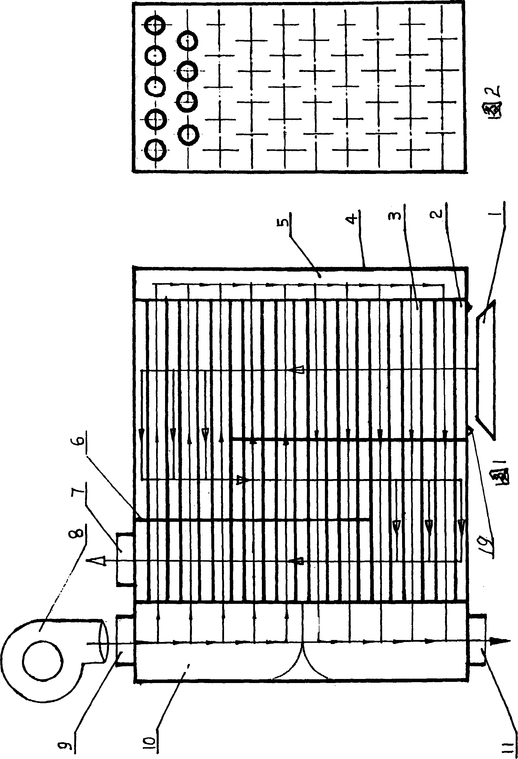
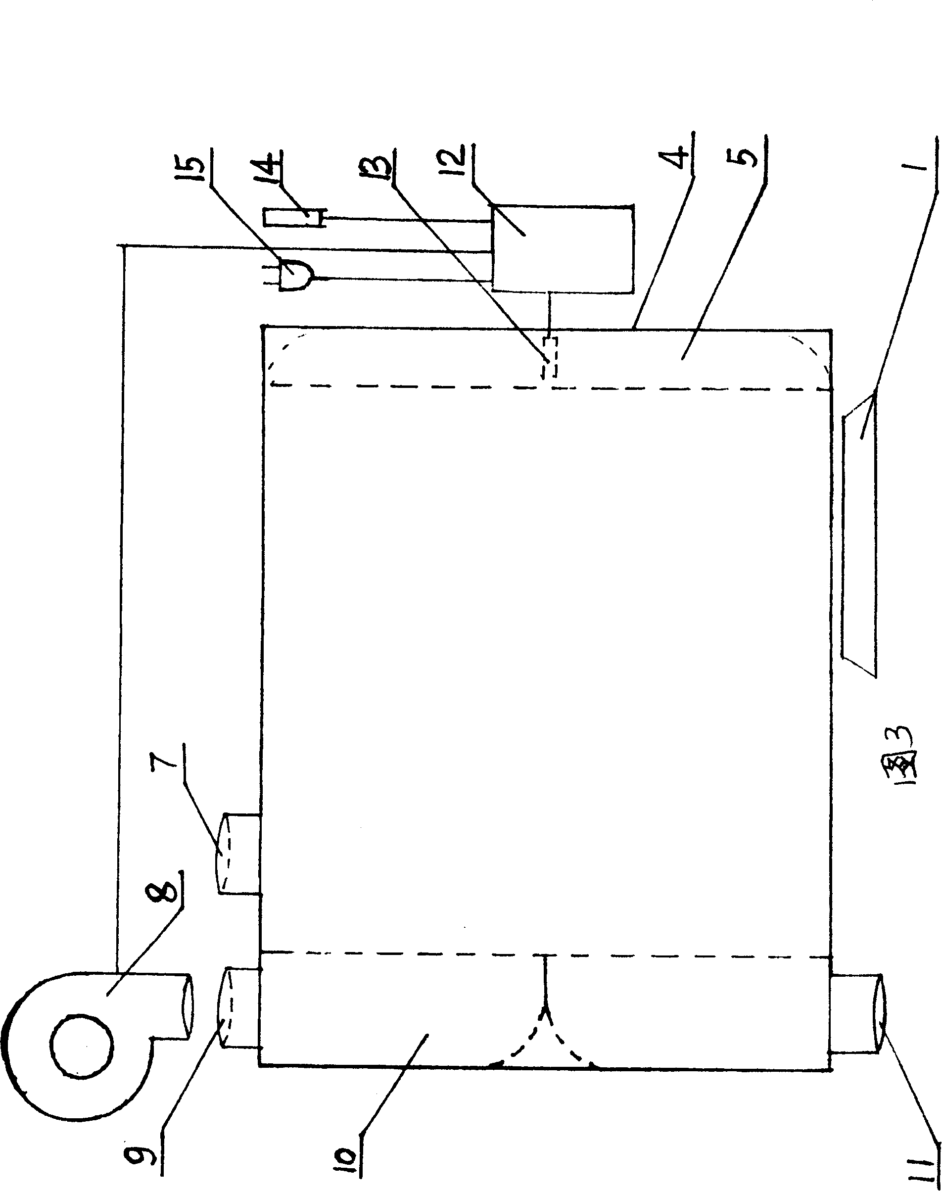
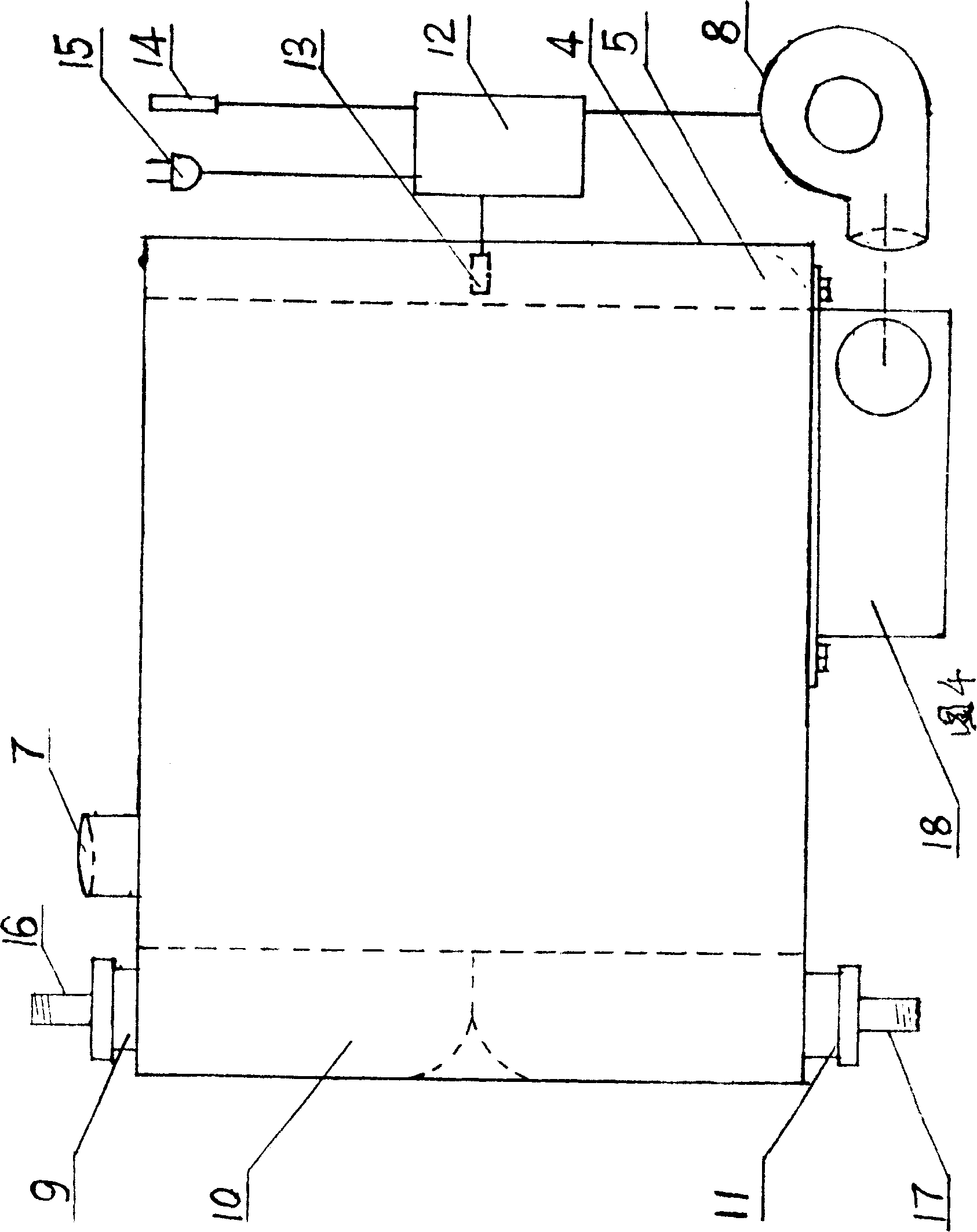
[0006] This wind exchange radiator has a casing 4 and flow channels 2, 3 in the casing, and is characterized in that: the heating fluid passage 2 separated by the conductor 23 and the heated air passage 5, 3, 10 are arranged in the casing, The inlet 9 of the air duct is the interface of the blower fan 8 . If the heating fluid channel is a hot water channel or a steam channel, the inlet and outlet of the hot water channel or the steam channel are respectively provided with threaded interfaces connected with pipelines of the central heating system. The air duct is composed of arranged pipelines 3 , a return air chamber 5 communicating with both ends of the pipelines, and an air inlet chamber 10 separated from an air outlet chamber. The rest of the housing is the heating fluid passage. The heating fluid channel is a gas channel 2 with baffles 6 . The inlet of the gas channel has an interface 19 communicating with the burner 1, and the outlet of the gas channel has an interface ...


PUM


Abstract

This invention is to resolve the question that the heat exchanging efficiency of existing heating radiator is low. It is a air exchanging radiator, which has body case and fluid channel inside of the body case. Heating fluid channel and heated air channel, which are separated by conductor, are arranged inside of the body case. The air channel has fan and joint with fan. The air in the heated air channel flows to exchange heat. The air is driven by the fan. It greatly increases the effect of heat exchanging and heating. It increases the heat efficiency.

Description

Technical field: [0001] The wind exchange radiator is a heat exchange heater that exchanges heat with forced air flow. Background technique: [0002] Existing household heating radiators, such as steam or hot water radiators, have a shell and a flow channel in the shell. The flow channel in the shell is only a steam or hot water channel, that is, the heating fluid channel of the radiator. The heated air is on the outside of the casing, and there is no specific passage outside the casing. The air can only be heated by flowing and exchanging heat outside the radiator by natural flow. The effect of heat dissipation and heating is poor, so the room must be equipped with a heating heat exchanger that occupies a large space, and each room must be equipped with a heating radiator. The installed heating radiators and pipelines affect the appearance of the room. If the heating radiators and pipelines are decorated and packaged according to the current habit, it will not only cost a...

Claims


Application Information

Patent Timeline
IPC IPC(8): F28D7/00
Inventor 秦子建
Owner 秦子建
Why Eureka
Try Eureka