
Image forming apparatus and process cartridge

The technology of an imaging device and a processing box, which is applied in the field of processing boxes, can solve the problems of increasing the transfer electric field, shortening the service life, increasing friction, etc.

Inactive Publication Date: 2008-04-23
FUJIFILM BUSINESS INNOVATION CORP
View PDF13 Cites 7 Cited by
  • Summary
  • Abstract
  • Description
  • Claims
  • Application Information

AI Technical Summary

Problems solved by technology

However, polymerized toner has a shape closer to a sphere than pulverized toner, and transfer electric field must be increased in many cases compared with pulverized toner, so that transfer ghost is more likely to occur
In addition, toner that is closer to a spherical shape has less rolling resistance and is easier to pass through cleaning parts such as cleaning blades, so poor cleaning is prone to occur
In order to prevent the toner from passing through the cleaning blade, the pressing force of the cleaning blade is set higher in many cases than in the case of pulverized toner, but as described above, when the blade is tightly pressed on the electrophotographic photosensitive When it is on the body, the friction between the scraper and the photoreceptor increases, resulting in accelerated wear of the photoreceptor and shortening the life of the photoreceptor

Method used


Image

  • Image forming apparatus and process cartridge
  • Image forming apparatus and process cartridge
  • Image forming apparatus and process cartridge

Examples


Embodiment 1

[0331] The photoreceptor 1 thus manufactured was mounted on DocuCentre Color 400CP (manufactured by Fuji Xerox Co., Ltd.). As the second exposure unit, the above light source 3 (E1L49-3G1A * -02) Installed between the cleaning unit and the charging unit to perform constant exposure in each imaging cycle with an exposure intensity of 200 μW within a width of 5 mm on the photoreceptor (erasing exposure can be regarded as exposure method 1). Thus, the imaging device in Example 1 was obtained.

[0332] Image quality evaluation :

[0333] The following evaluations were performed in a low temperature and low humidity (10°C and 20% relative humidity) and high temperature and high humidity (30°C, 85% relative humidity) environment. First, in a low temperature and low humidity (10° C. and 20% relative humidity) environment, a 10-page continuous imaging test was performed to evaluate the ghost, image density, and streaks of the image on the 10th page. After that, a 10,000-page imaging tes...

Embodiment 2

[0356] In Example 1, before the initial printing of 10 pages, the second exposure unit was used to pre-expose the photoreceptor in the process of 100 revolutions, and then the exposure intensity of 200μW was applied to the photoreceptor within a width of 5mm on each Constant exposure (pre-exposure + erase exposure, can be regarded as exposure method 2) during the imaging cycle. The imaging apparatus in Example 2 was obtained in the same method as in Example 1 except for the above-mentioned cases. The image quality evaluation test of the obtained imaging device was performed in the same manner as in Example 1. The results obtained are shown in Table 18.

Embodiment 3~17 and comparative example 1~9

[0358] The imaging devices of Examples 3 to 17 and Comparative Examples 1 to 9 were manufactured in the same method as in Example 1 and subjected to image quality evaluation tests, except that the photoreceptor, exposure light source, and exposure were changed as shown in Table 18. Combination of intensity and exposure method. The results obtained are shown in Table 18.

[0359]


PUM


Abstract

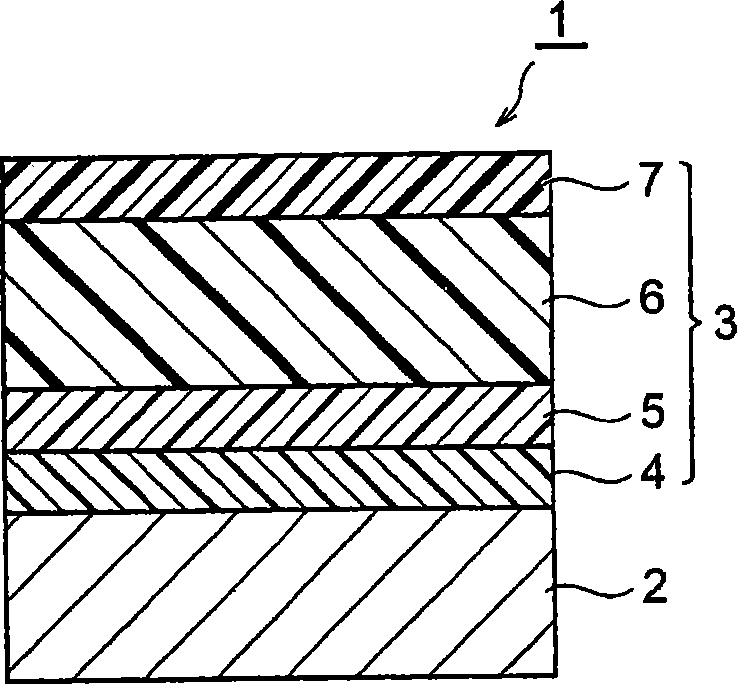
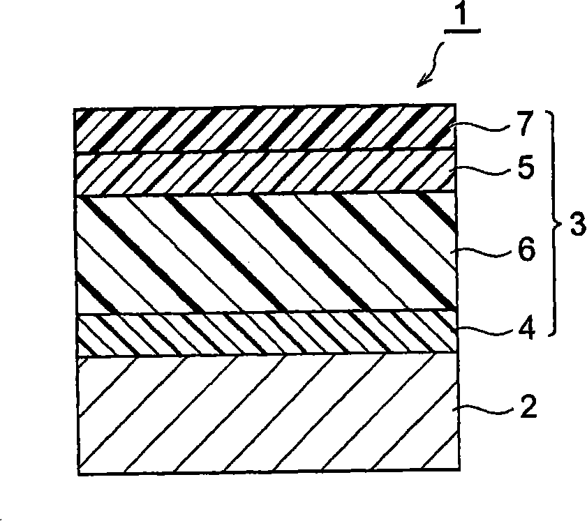
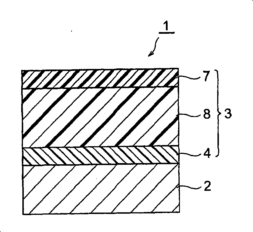
An image forming apparatus includes: an electrophotographic photoreceptor including a conductive support and a photosensitive layer including an outermost surface layer capable of transporting a charge, the layer being farthest from the conductive support and containing a resin having a crosslinking structure; a charging unit that charges the electrophotographic photoreceptor; a first exposure unit that exposes the electrophotographic photoreceptor to form an electrostatic latent image on the electrophotographic photoreceptor charged; a developing unit that develop the electrostatic latent image with a toner to form a toner image; a transfer unit that transfer the toner image from the electrophotographic photoreceptor to a medium to be transferred; and a second exposure unit that uniformly expose the electrophotographic photoreceptor, the outermost surface layer absorbing exposure light of the second exposure unit and having a maximum absorbance of about 0.05 or less in the entire wavelength range of the exposure light.

Description

Technical field [0001] The present invention relates to an image forming apparatus that uses an electrophotographic method including charging, exposure, development, and transfer to form an image, and the present invention also relates to a process cartridge. Background technique [0002] An image forming apparatus adopting an electrophotographic method generally has the following constitution and steps. First, a charging unit is used to uniformly charge the surface of the electrophotographic photoreceptor (hereinafter sometimes referred to as "photoreceptor") to have a predetermined polarity and potential, and the charge on the surface of the photoreceptor after being charged is obtained by image exposure. It is selectively removed to form an electrostatic latent image. Subsequently, a developing unit is used to attach toner to the electrostatic latent image to develop the latent image into a toner image, and the toner image is transferred to the transfer medium using a transfer...

Claims


Application Information

Patent Timeline
Patent Type & Authority Applications(China)
IPC IPC(8): G03G15/04G03G15/00G03G5/06G03G21/18
CPCG03G5/0666G03G21/08G03G5/14795G03G15/751G03G5/14791G03G5/0614G03G5/0592G03G5/0664G03G5/0596G03G5/09G03G5/0642G03G5/0607G03G5/0625
Inventor 额田克己山田涉古城由贵子山下敬之
Owner FUJIFILM BUSINESS INNOVATION CORP
Learn More