Eureka AIR delivers breakthrough ideas for toughest innovation challenges, trusted by R&D personnel around the world.

Temperature fuse connection structure

A technology of thermal fuse and connection structure, applied in the direction of protection switch operation/release mechanism, emergency protection device, heating/cooling contact switch, etc.

Inactive Publication Date: 2008-04-23
游聪谋
View PDF0 Cites 4 Cited by
  • Summary
  • Abstract
  • Description
  • Claims
  • Application Information

AI Technical Summary

Problems solved by technology

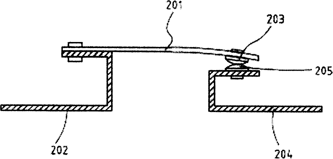
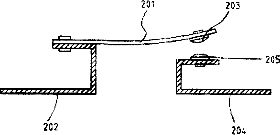
[0011] The present invention is to solve the problem that a contact shrapnel used as a temperature-sensing tripping power-off device in the existing temperature-sensing power-off protector of a single electronic product cannot accurately and effectively set the induction temperature value of power-off, and when the current is overloaded and overheated , when th

Method used


Image

  • Temperature fuse connection structure
  • Temperature fuse connection structure
  • Temperature fuse connection structure

Examples


Example Embodiment

[0057] In order to reveal the purpose, features and effects of the present invention in detail, the present invention will be further described in detail according to the following preferred specific embodiments and accompanying drawings as follows:

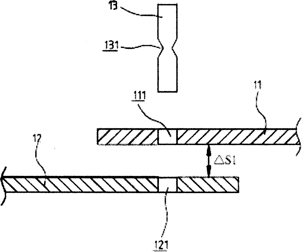
[0058] Such as image 3 , Shown in 4, is an anatomical view and a combined cross-sectional view of an embodiment of the present invention; Figure 5 When the current is overloaded or the circuit is overheated, the hot melt metal is heated and the temperature rises and melts and breaks. The free ends of the two terminals are not connected to each other, and the circuit becomes an OFF state schematic diagram; The temperature fuse connection structure mainly includes two terminals (11, 12) and a hot melt metal (13); among them,

[0059] The two terminals (11, 12) are fixedly arranged in the circuit line, and the two free ends of the two terminals (11, 12) are respectively provided with traversable openings (111, 121), the openings (111,...


PUM


Abstract

In the invention, a hot melt metal rivet is used to connect two separated terminals in order to make said two terminals to be connected so as to turn-on the circuit; a distance is kept between the two free ends of said two terminal; when the current is overloaded or overheated or the ambient temperature is too high, the hot melt metal is heated and the temperature raises so as to turn off circuits.

Description

technical field [0001] The invention relates to a connection structure of a temperature fuse, which uses a hot-melt metal riveting to connect two separated terminals in the circuit, so that the two terminals are electrically connected and connected to the circuit. When the current is overloaded and the circuit is overheated, the thermal When the molten metal is heated, its temperature rises and it melts and fractures, making the circuit in an OFF state. Background technique [0002] The use of electricity has become an indispensable part of modern human society. The use of electric equipment surrounds life, especially in computerized and informationized industries, homes, transportation, education, entertainment, etc., without electricity. In contrast, the safe use of electricity is something that modern people cannot but be cautious about. [0003] Generally speaking, there is a main switch for power control in the overall circuit circuit of the power supply unit. Usually ...

Claims


Application Information

Patent Timeline
IPC IPC(8): H01H85/02H01H85/143H01H85/08H01H85/06H01H37/76H01H71/20
Inventor 游聪谋
Owner 游聪谋
Why Eureka
Eureka Blog
Learn More