
Ejection device for a movable part of a piece of furniture

A technology for furniture parts and push-out devices, applied in furniture parts, wing fan parts, household appliances, etc., can solve the problems of slow push-out process and large drive unit, and achieve the effect of reducing load and mechanical vibration.

Active Publication Date: 2008-04-23
JULIUS BLUM GMBH
View PDF0 Cites 0 Cited by
  • Summary
  • Abstract
  • Description
  • Claims
  • Application Information

AI Technical Summary

Problems solved by technology

[0005] In the prior art this has the disadvantage that only small forces F can be transmitted to the movable furniture part due to the large moment arm r
Especially in the initial acceleration phase, in which the movable furniture part has to be accelerated from a standstill against its inertia, which results in a high load on the drive unit and, due to the low acceleration, a slow ejection process

Method used


Image

  • Ejection device for a movable part of a piece of furniture
  • Ejection device for a movable part of a piece of furniture
  • Ejection device for a movable part of a piece of furniture

Examples


Embodiment Construction

[0033] Note that the same scale is chosen in all figures.

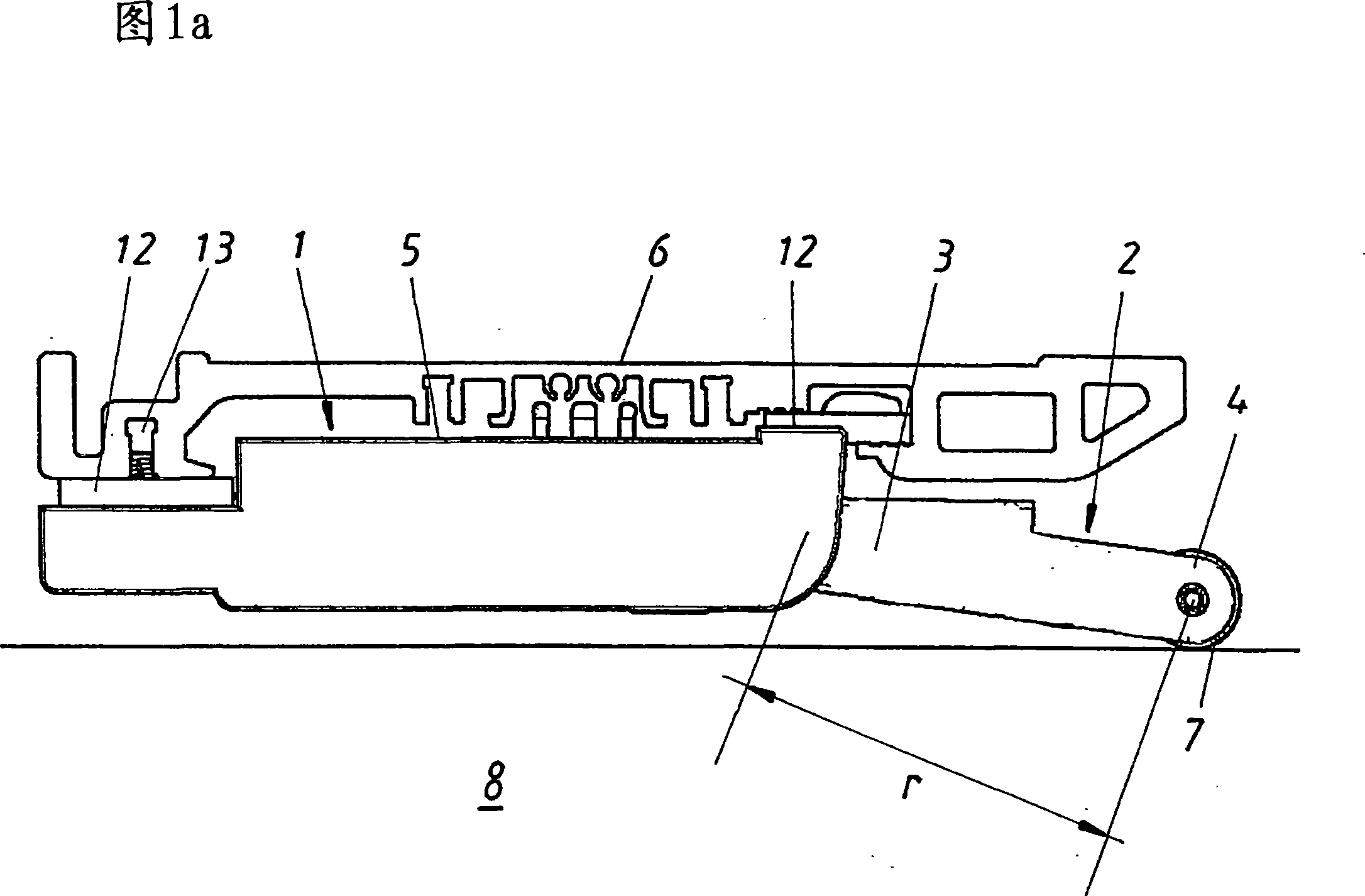
[0034] FIG. 1 a schematically shows an ejector device 1 with a housing 5 on which a lever 2 is mounted so that it can rotate to a limited extent. The ejection device 1 is mounted on a support element 6 and includes an electric motor for driving the lever 2 . The carrier element 6 is arranged on a furniture body, not shown in detail. The lever 2 comprises a lever body 3 and a free lever end 4 . A roller 7 is arranged on the free lever end 4 . In FIG. 1 a the movable furniture part 8 is a drawer which is located in the furniture body in the closed end position. Roller 7 leans against on the back wall of drawer.

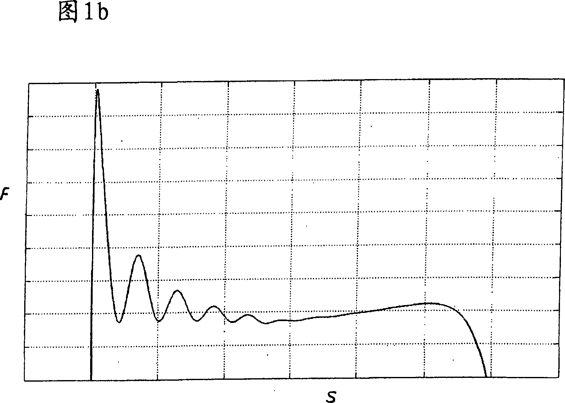
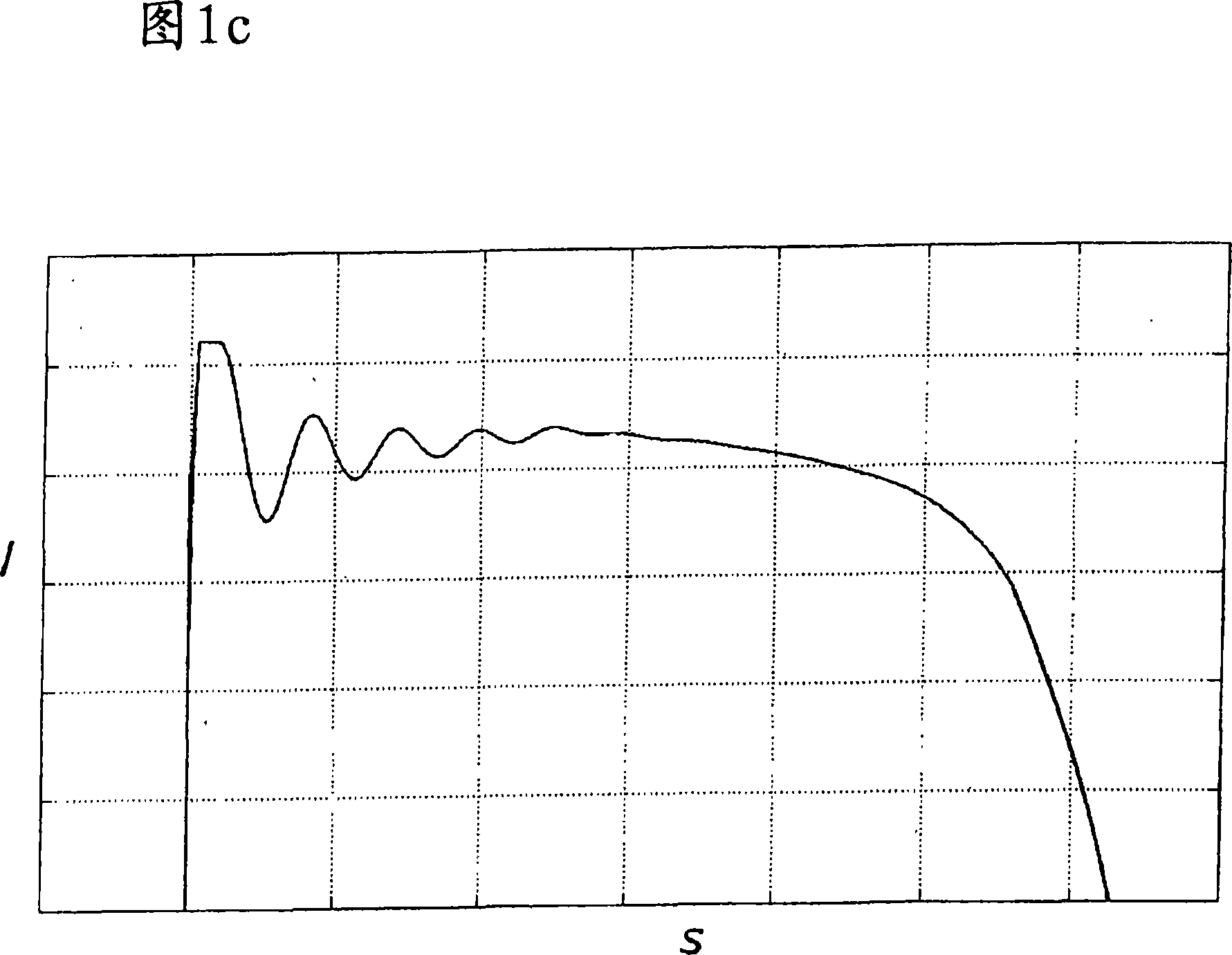
[0035] FIG. 1b shows a graph of the force F exerted by the lever on the rear wall of the drawer versus the stroke s. The travel s is here the distance covered by the drawer rear wall from the closed end position to lifting by the lever 2 . FIG. 1c shows a graph of the current I fed to the motor versus the...


PUM


Abstract

Disclosed is an ejection device ( 1 ) for a movable part ( 9 ) of a piece of furniture. Said election device ( 1 ) comprises a lever ( 2 ) for transmitting force to the movable part ( 8 ) of the piece of furniture. The lever ( 2 ) encompasses a lever member ( 3 ) which is mounted so as to be rotatable by a limited degree about an axis of rotation while having a free lever end ( 4 ). The lever member ( 3 ) is provided with a section ( 9 ) that is spaced apart from the axis of rotation and the free lever end ( 4 ) and is embodied in a curved manner.

Description

technical field [0001] The invention relates to an ejection device for movable furniture parts, comprising a lever for transmitting force to the movable furniture part, wherein the lever has a lever body, which on the one hand is rotatable to a limited extent about an axis of rotation Ground bearing and on the other hand have a free lever end. Background technique [0002] Such ejection devices have been used for a long time. In this case, a torque is applied to the lever body via a mostly electrical drive unit. When the ejection device is arranged in a piece of furniture, the force F exerted by the lever body on the movable furniture part depends on the moment arm r due to the formula F=M / r. [0003] For a torque M predetermined by the drive unit, the larger the moment arm r, the smaller the force F exerted on the movable furniture part. The magnitude of the moment arm r is of course equal to the distance between the axis of rotation and the position where the lever body...

Claims


Application Information

Patent Timeline
Patent Type & Authority Applications(China)
IPC IPC(8): A47B88/04
CPCE05F15/127E05Y2400/326E05Y2600/458A47B88/0477E05Y2201/426A47B88/0414E05Y2900/20E05F11/54E05Y2800/00E05Y2201/434A47B88/457E05F15/63A47B88/463
Inventor 埃德加·胡伯尔
Owner JULIUS BLUM GMBH
Learn More