
Spinning machine having yarn slack elimination device

A spinning machine and relaxation technology, which is applied in the field of spinning machines, can solve the problems of time-consuming, difficult mechanism, and inability to fine-tune the rotation torque change in spinning, and achieve the effect of stabilizing the rotation resistance and forming stable quality.

Active Publication Date: 2011-03-23
MURATA MASCH LTD
View PDF1 Cites 0 Cited by
  • Summary
  • Abstract
  • Description
  • Claims
  • Application Information

AI Technical Summary

Problems solved by technology

[0008] However, in the Figure 5 and Image 6 In the magnetic tensioner device shown in the figure, it is necessary to adjust each spindle when the upper machine is changed, etc., and when the rotational torque of multiple spindles is to be changed at the same time, which requires a lot of work.
Furthermore, it is mechanically difficult to change the rotational torque while continuing to wind the yarn, and it is not possible to perform fine adjustments during spinning and actively change the rotational torque.

Method used


Image

  • Spinning machine having yarn slack elimination device
  • Spinning machine having yarn slack elimination device
  • Spinning machine having yarn slack elimination device

Examples


Embodiment Construction

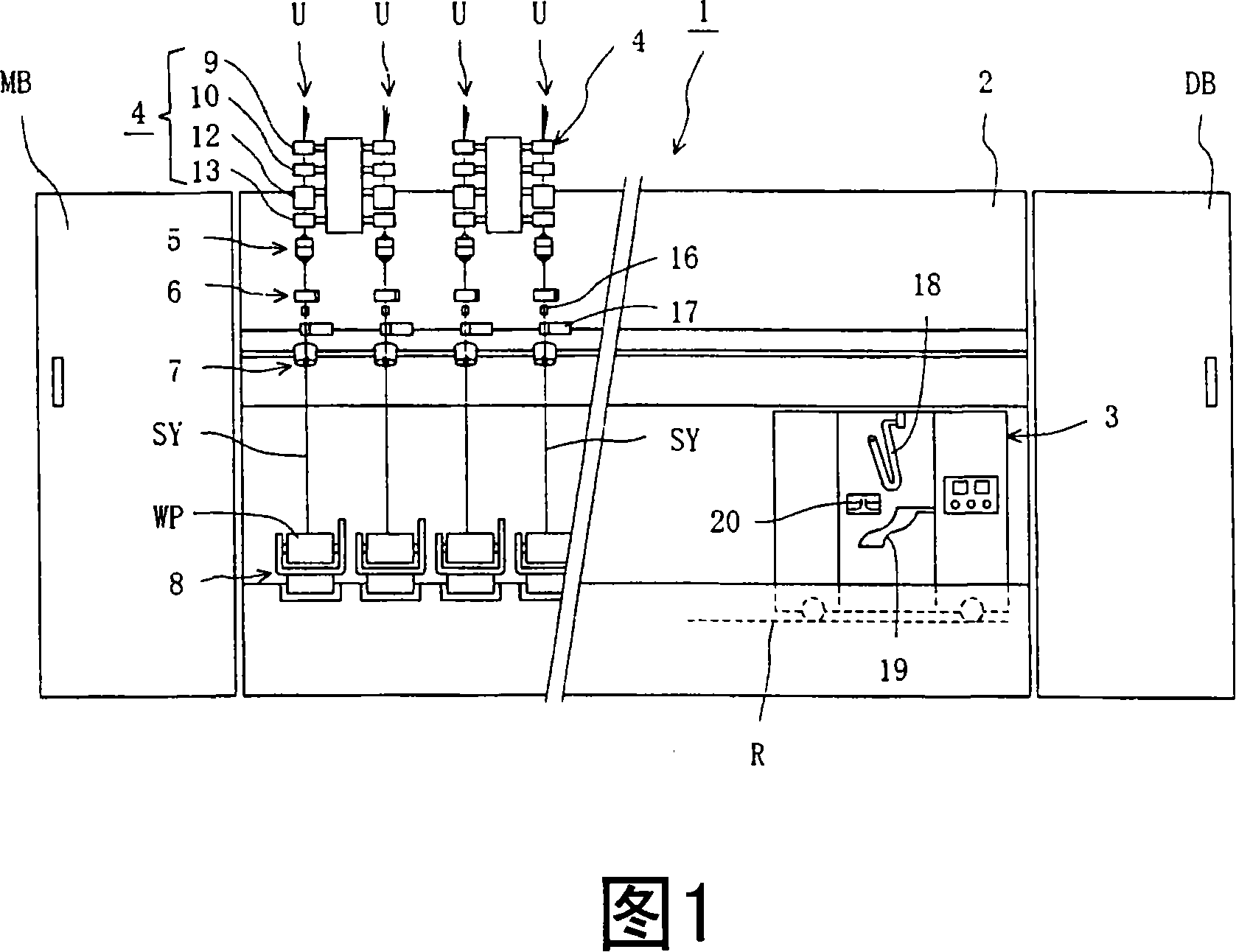
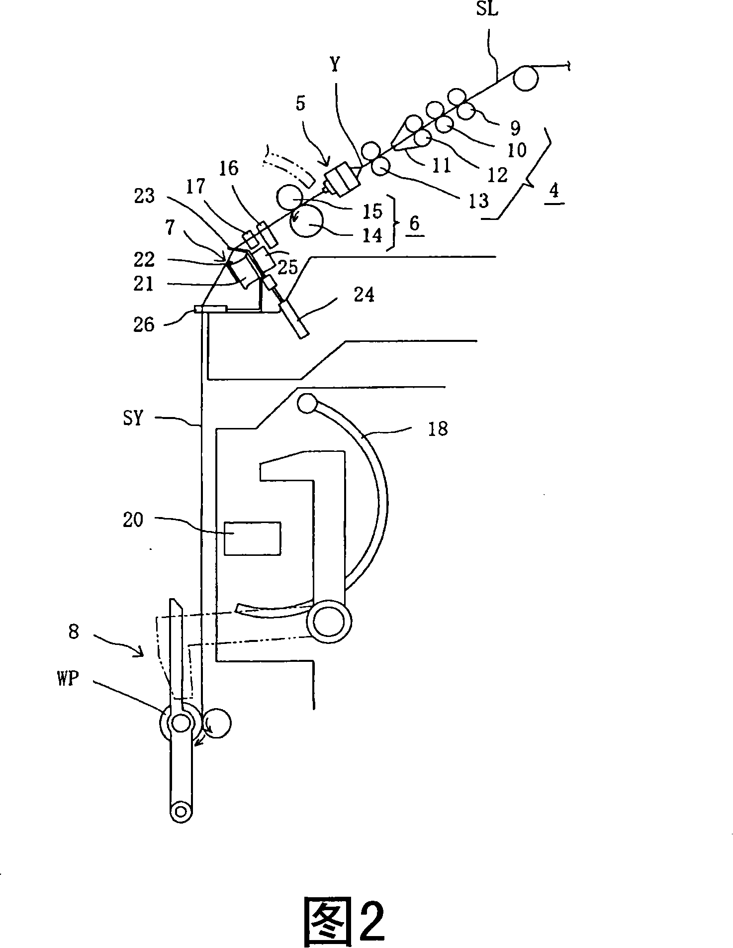
[0024] Hereinafter, the yarn slack removal device incorporating the electromagnetic tensioner of the present invention will be described in detail based on specific examples shown in the drawings. figure 1 It is a schematic overall front view showing an example of a spinning machine to which the present invention is applied, figure 2 so figure 1 A schematic side view of a section of a spinning machine.

[0025] First, the spinning machine 1 to which the present invention is applied will be described. The spinning machine 1 such as figure 1 As shown, a plurality of spinning units U are arranged along the length direction of the machine between the prime mover box MB and the dust box DB. The spinning machine 1 is provided with a rail R along the direction in which the above-mentioned spinning units U are arranged, and is configured so that the yarn joining cart 3 can reciprocate on the rail R in the left-right direction. The piecing trolley 3 travels toward the spinning ...


PUM


Abstract

It is an object of the present invention to provide a spinning machine having yarn slack eliminating device provided therein with an electromagnetic tensor capable of realizing a stable rotation resistance with respect to a yarn slack eliminating roller of the yarn hooking member, and capable of forming a package of stable quality. The yarn slack eliminating device includes a rotating and drivingsource (25), a yarn slack eliminating roller (21) which is rotated and driven by the rotating and driving source (25), and a yarn hooking member (22) which is mounted on the yarn slack eliminating roller (21) such that the yarn hooking member (22) can relatively rotate concentrically with the yarn slack eliminating roller (21), the yarn slack eliminating roller (21) is provided with magnetic field forming means (34) by electromagnet so that a magnetic field is applied to the yarn hooking member (22), a rotation torque is generated between the yarn slack eliminating roller (21) and the yarn hooking member (22) by the magnetic field generated by the magnetic field forming means (34), and the rotation torque is controlled by input control to the electromagnet.

Description

technical field [0001] The present invention relates to a spinning machine provided with a yarn slack removing device for removing slack in a yarn generated between the spinning machine and a package winding device in a textile machine such as a spinning machine. Background technique [0002] Conventionally, in a high-speed spinning machine such as an air-type spinning machine that winds a spun yarn to form a package, for example, if a yarn defect is detected, the yarn defect is detected with a cutter. After the cutting mechanism cuts and removes the yarn, the yarn end sent from the spinning device and the yarn end on the package side are joined by the yarn joining device. Since the above-mentioned piecing operation needs to be performed while the winding of the yarn is stopped, it is necessary to remove the slack of the yarn between the spinning device and the package winding device. [0003] As a technique for removing such slack in the yarn, a yarn slack removing device ...

Claims


Application Information

Patent Timeline
Patent Type & Authority Patents(China)
IPC IPC(8): D01H13/10D01H13/16B65H59/10B65H63/02
CPCD01H13/104D01H13/10B65H2701/31B65H51/22
Inventor 上田健一
Owner MURATA MASCH LTD
Learn More