Belt wheel for V-belt type automatic variable speed gear

A technology of automatic speed change device and pulley, which is applied in the direction of transmission device, portable lifting device, hoisting device, etc., can solve the problem of difficulty in forming durable pulleys, etc. Effect

Inactive Publication Date: 2008-04-30
YAMADA SEISAKUSHO KK
View PDF2 Cites 11 Cited by
  • Summary
  • Abstract
  • Description
  • Claims
  • Application Information

AI Technical Summary

Problems solved by technology

[0008] That is, it is difficult to form a practical pulley with durability if only the hu

Method used


Image

  • Belt wheel for V-belt type automatic variable speed gear
  • Belt wheel for V-belt type automatic variable speed gear
  • Belt wheel for V-belt type automatic variable speed gear

Examples


Embodiment Construction

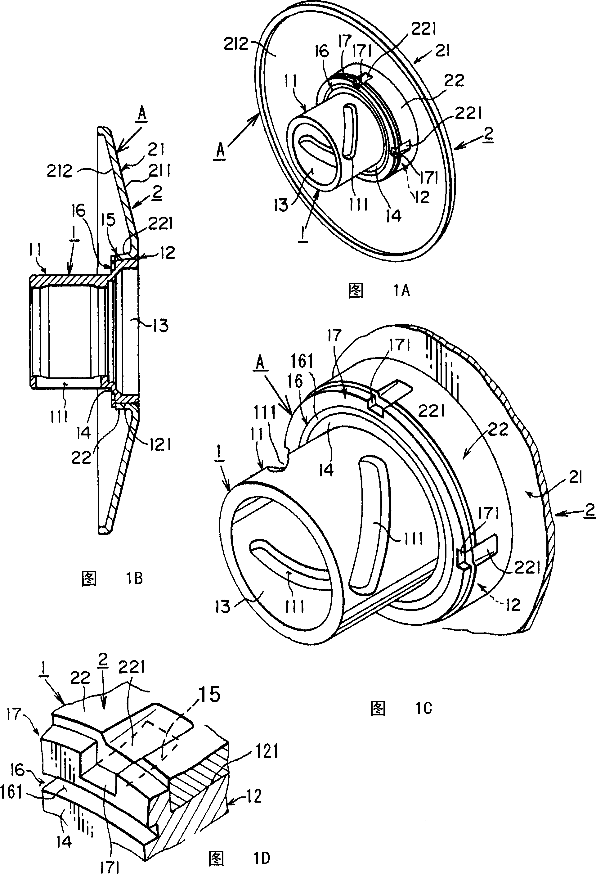
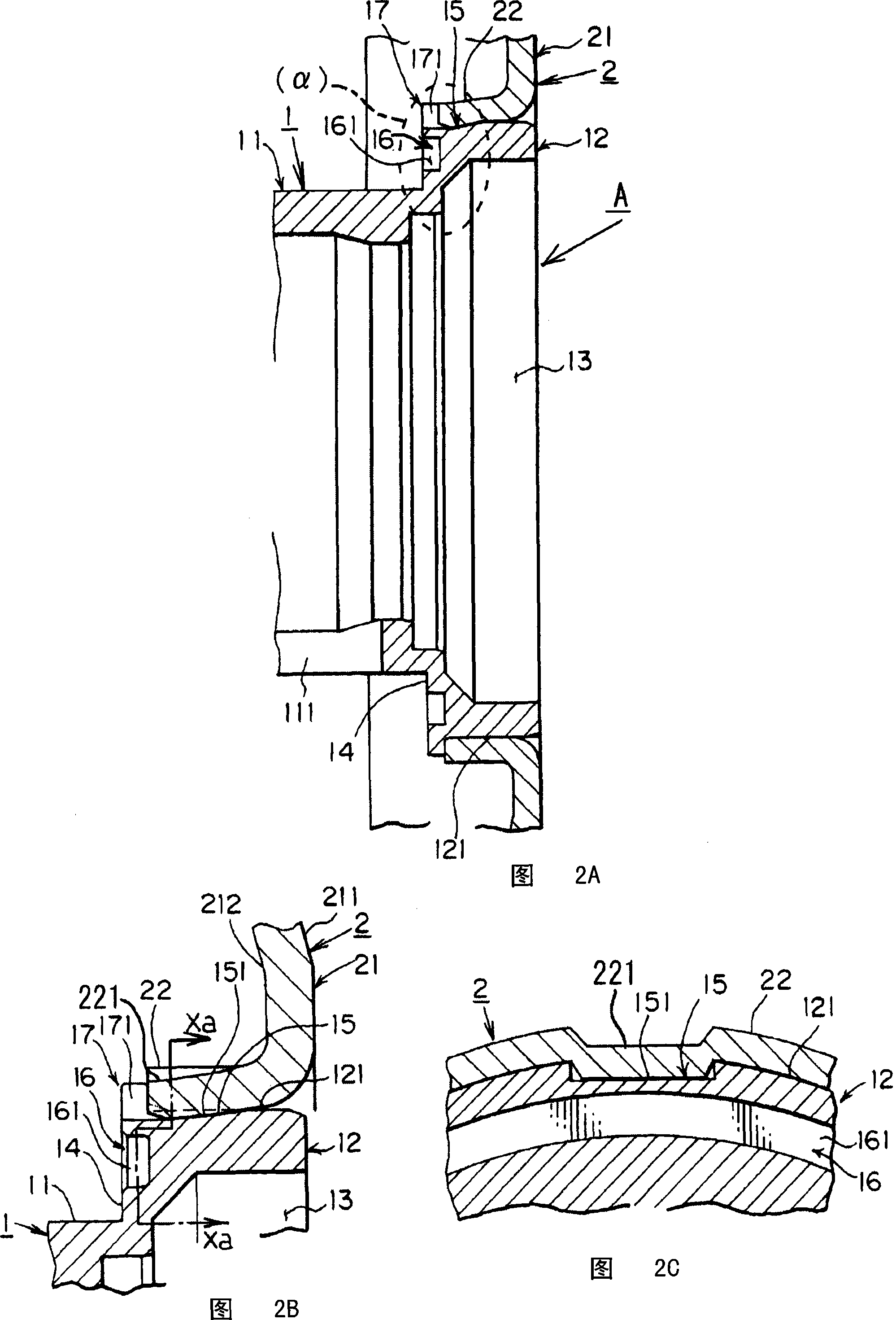
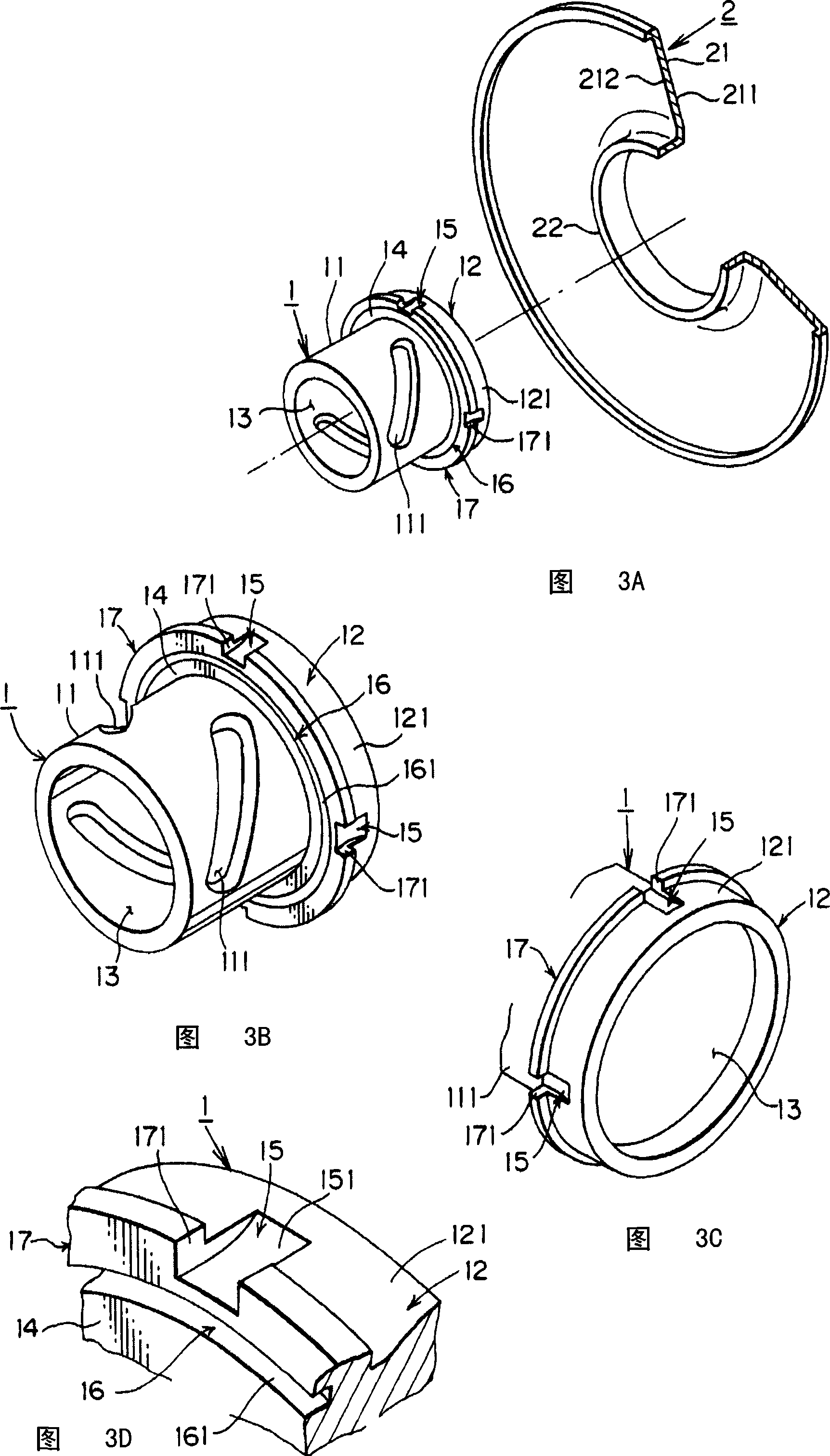
[0039] Hereinafter, the present invention will be described with reference to the drawings. First, Fig. 11 shows the situation in which the present invention is mounted on a V-belt type automatic transmission. The driven pulley mainly includes a movable pulley half body A, a fixed pulley half body 3 and a driven shaft 4 as shown in FIG. 11 . The movable sheave half A includes a hub member 1 and a movable sheave surface 2 .

[0040]As shown in FIGS. 3 and 4 , the hub member 1 includes a hub shaft portion 11 and a large-diameter cylindrical portion 12 formed on one end side of the hub shaft portion 11 in the axial direction. The large-diameter cylindrical portion 12 is formed in a substantially flat cylindrical shape, and is formed to have a larger diameter than the above-mentioned hub shaft portion 11 (see FIG. 4A ). Furthermore, the above-mentioned large-diameter cylindrical portion 12 is formed as a disc perpendicular to the axial direction of the above-mentioned hub member...


PUM


Abstract

A V-belt automatic shift pulley is provided, pulley surface can be mounted simply and quickly with respect to a hub shaft, and the combination is firm. Parts (1) forming the hub element comprise a hub shaft (11), a large-diameter circular cylinder part (12) disposed at one side terminal in the axial direction of the hub shaft (11), a step surface (14) formed between the hub shaft (11) and the large-diameter circular cylinder part (12), a groove formed in an axial direction at the peripheral lateral surface of the large-diameter circular cylinder part (12). A movable pulley surface (2) is formed, and a circular cylinder combination portion (22) is formed at the diameter center of the pulley surface (21). The circular cylinder combination portion (22) is inserted by the large-diameter circular cylinder part (12), and the wall shape of the circular cylinder combination portion (22) along said groove portion is riveted.

Description

technical field [0001] The present invention relates to a pulley of a V-belt automatic transmission. In the V-belt automatic transmission, the surface of the pulley can be easily and quickly installed relative to the hub shaft and the joint state can be made very firm. Background technique [0002] Patent Document 1 discloses that, in the manufacture of the pulley of the V-belt type automatic transmission, laser welding, plasma welding, etc. to integrate. Furthermore, Patent Document 2 discloses a structure in which a cylinder constituting a part of the oil chamber on the back side of the pulley is fixed to the back side of the movable pulley by caulking. [0003] Patent Document 1: Japanese Unexamined Patent Publication No. 10-103438 [0004] Patent Document 2: Japanese Unexamined Patent Publication No. 9-329208 [0005] First, in Patent Document 1, when manufacturing the pulley by welding the above-mentioned driven surface and the hub into one, in order to avoid deforma...

Claims


Application Information

Patent Timeline
IPC IPC(8): F16H55/36F16H9/12
Inventor 川岛芳德
Owner YAMADA SEISAKUSHO KK
Why Eureka
Try Eureka