

Covering board component
A cover plate and component technology, which is applied to battery pack parts, structural parts, electrical components, etc., can solve the problems that the explosion-proof cover plate cannot be used with batteries and does not have safety devices, so as to achieve good sealing, convenient adjustment, and convenient processing and manufacturing Effect
- Summary
- Abstract
- Description
- Claims
- Application Information
AI Technical Summary
Problems solved by technology
Method used
Image

Examples
Embodiment 1
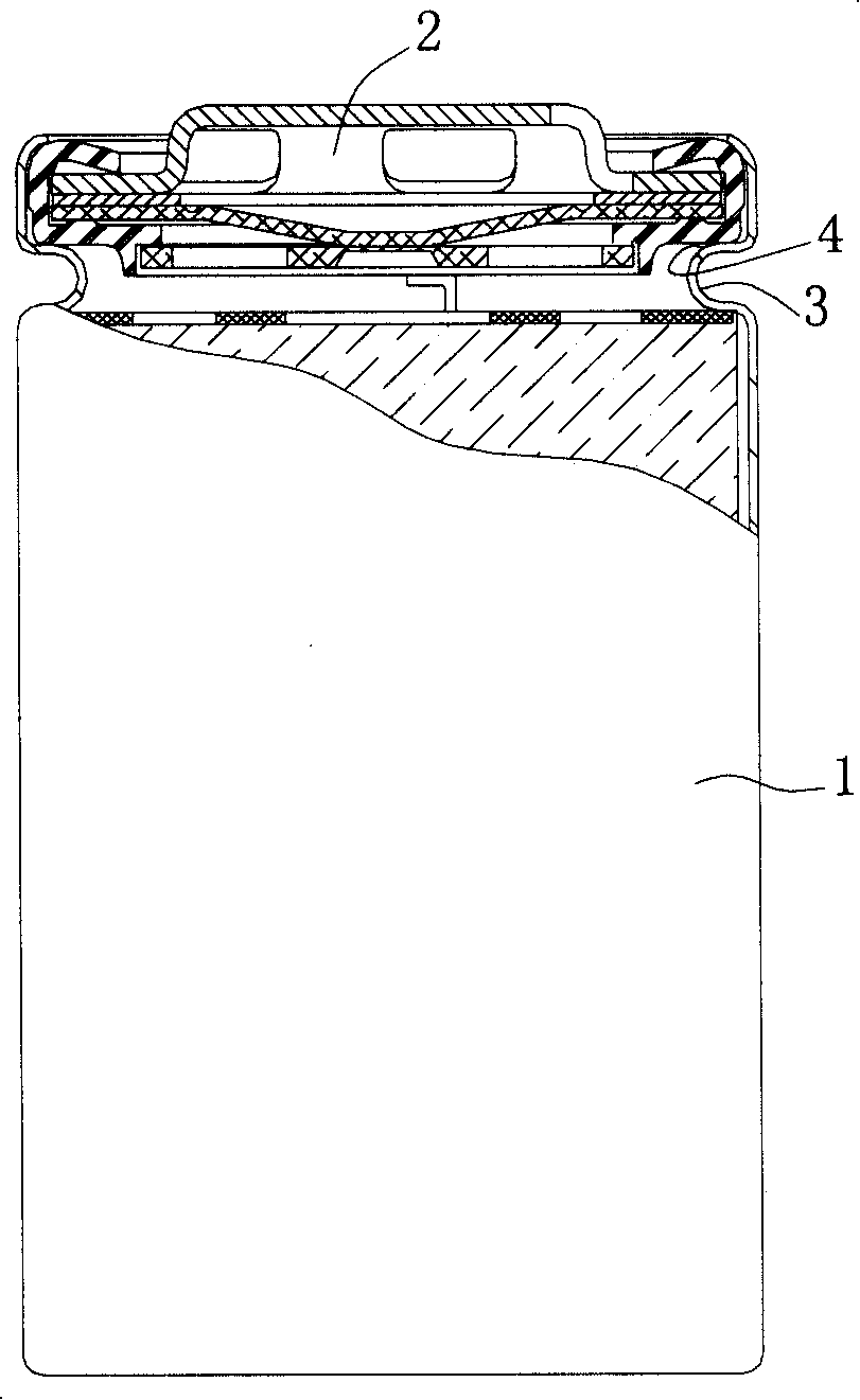
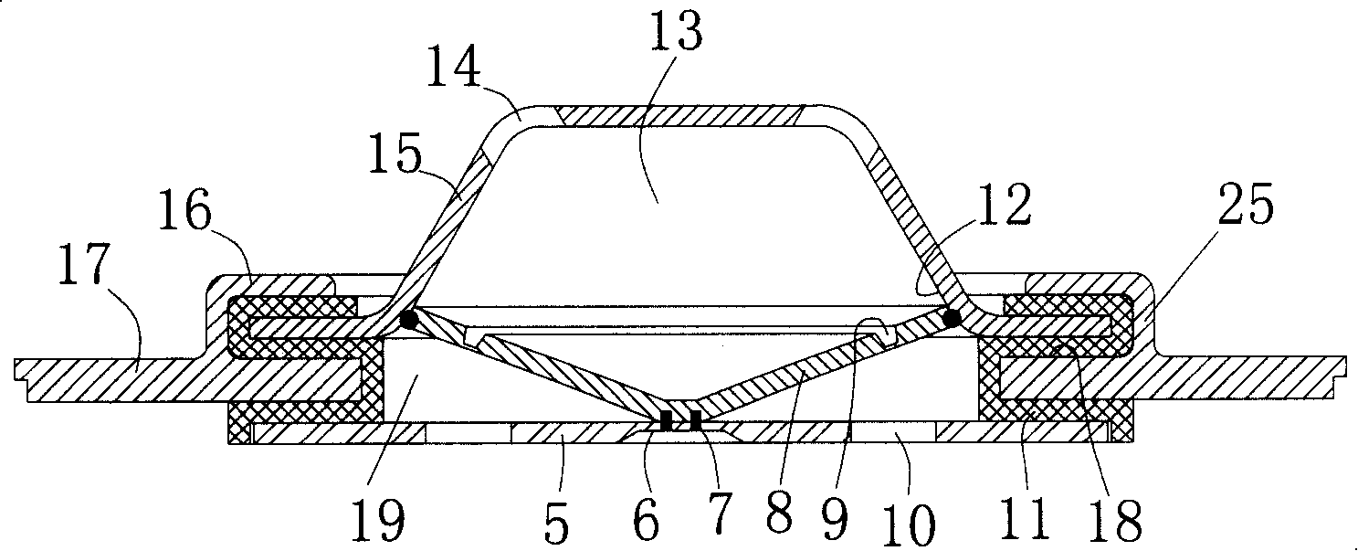
[0048] Embodiment 1. A cover plate assembly combined with Figure 2-4 with Figure 10As shown, it includes an assembly seat 17 , a cover plate 15 , an insulator 11 , an explosion-proof membrane 8 and a pull plate 5 . The assembly seat 17 is an assembly plate. The assembly plate 17 has a cover plate hole 19 , and around the cover plate hole 19 there is a cylinder 25 extending upwards, and a cavity 28 communicating up and down is formed in the cylinder 25 . There is an annular table top 18 around the cover plate hole 19 in the cylinder, and the upper part of the cylinder 25 forms an annular sealing groove 29 on the inner wall of the cavity 28 of the assembly seat 17 by bending inwardly (bending portion 16 ). There is a pressure relief hole 14 on the cover plate 15 as the electrode of the drawn current, the periphery of the cover plate 15 is insulated by the insulator 11 and sealed and fixed in the annular sealing groove 29, the cover plate 15 protrudes outwards to form a cavity...
Embodiment 2
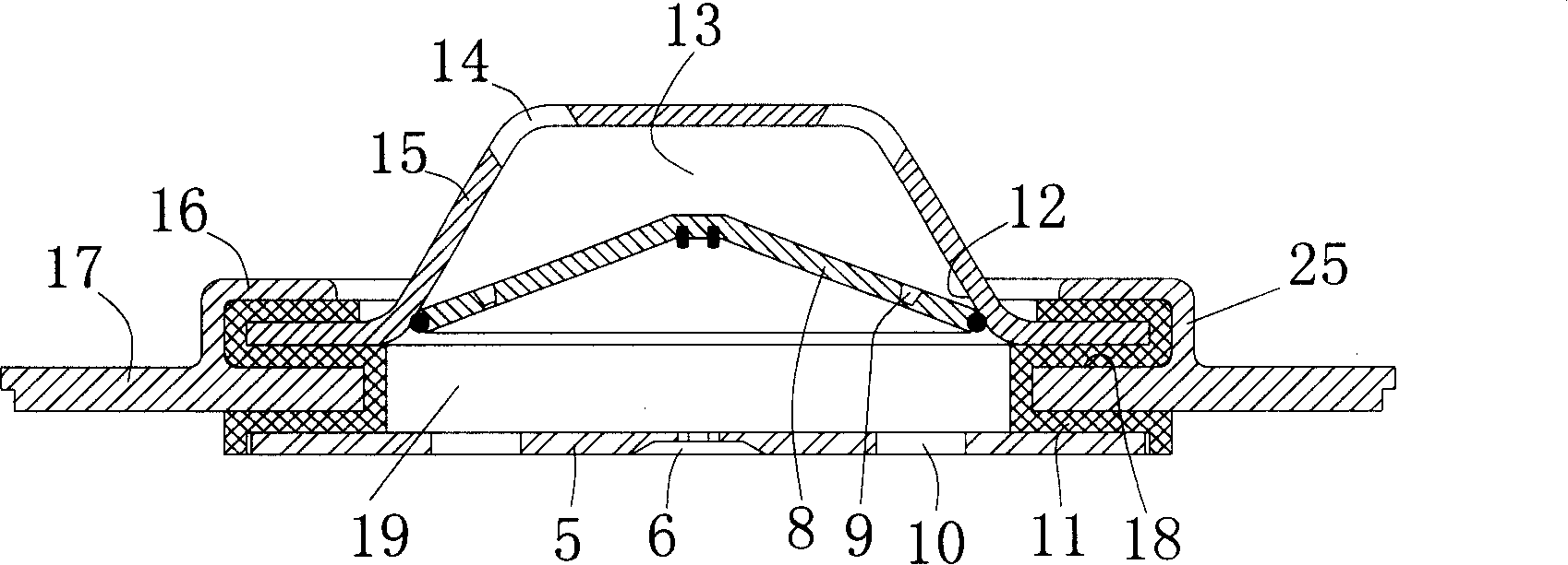
[0052] Embodiment 2, another cover assembly, combined with Figure 5 with Figure 10 As shown, it includes an assembly seat 17 , a cover plate 15 , an insulator 11 , an explosion-proof membrane 8 and a pull plate 5 . The assembly seat 17 is an assembly plate. The assembly plate 17 has a cover plate hole 19 , and around the cover plate hole 19 there is a cylinder 25 extending upwards, and a cavity 28 communicating up and down is formed in the cylinder 25 . There is an annular table top 18 around the cover plate hole 19 in the cylinder, and the upper part of the cylinder 25 forms an annular sealing groove 29 on the inner wall of the cavity 28 of the assembly seat 17 by bending inwardly (bending portion 16 ). There is a pressure relief hole 14 on the cover plate 15 as the electrode for extracting the current. The peripheral edge of the explosion-proof membrane 8 and the peripheral edge of the cover plate 15 are clamped and fixed in the annular sealing groove 29 by overlapping, p...
Embodiment 3
[0053] Embodiment 3, yet another cover plate assembly, combined with Image 6 with Figure 11 As shown, it includes an assembly seat 17 , a cover plate 15 , an insulator 11 , an explosion-proof membrane 8 and a pull plate 5 . The assembly seat 17 is an assembly plate. The assembly plate 17 has a cover plate hole 19 . Around the cover plate hole 19 there is a cylinder 25 extending downward, and a cavity 28 communicating up and down is formed in the cylinder 25 . There is an annular table top 18 around the cover plate hole 19 in the cylinder, and the lower part of the cylinder 25 forms an annular sealing groove 29 on the inner wall of the cavity 28 of the assembly seat 17 by bending inwardly (bending portion 16 ). There is a pressure relief hole 14 on the cover plate 15 as the electrode for extracting the current. The peripheral edge of the explosion-proof membrane 8 and the peripheral edge of the cover plate 15 are clamped and fixed in the annular sealing groove 29 by overlapp...
PUM
 Abstract
Description
Claims
Application Information