Micro-channel filter tank with four levels of spacing-decreasing multi-cylindrical array structures

An array structure, micro-channel technology, applied in the direction of laboratory equipment, laboratory containers, chemical instruments and methods, etc., can solve the problems of channel scrapping, microfluidic channel blockage failure, etc., to facilitate processing and manufacturing, avoid normal The effect of flow disturbance

Active Publication Date: 2018-05-08
BEIJING UNIV OF TECH
View PDF2 Cites 4 Cited by
  • Summary
  • Abstract
  • Description
  • Claims
  • Application Information

AI Technical Summary

Problems solved by technology

Once solid waste larger than the minimum size of the channel structure enters the microfluidic channel, i

Method used


Image

  • Micro-channel filter tank with four levels of spacing-decreasing multi-cylindrical array structures
  • Micro-channel filter tank with four levels of spacing-decreasing multi-cylindrical array structures
  • Micro-channel filter tank with four levels of spacing-decreasing multi-cylindrical array structures

Examples


Example Embodiment

[0018] The working process and effects of the invention will be further explained below in conjunction with the structural drawings.

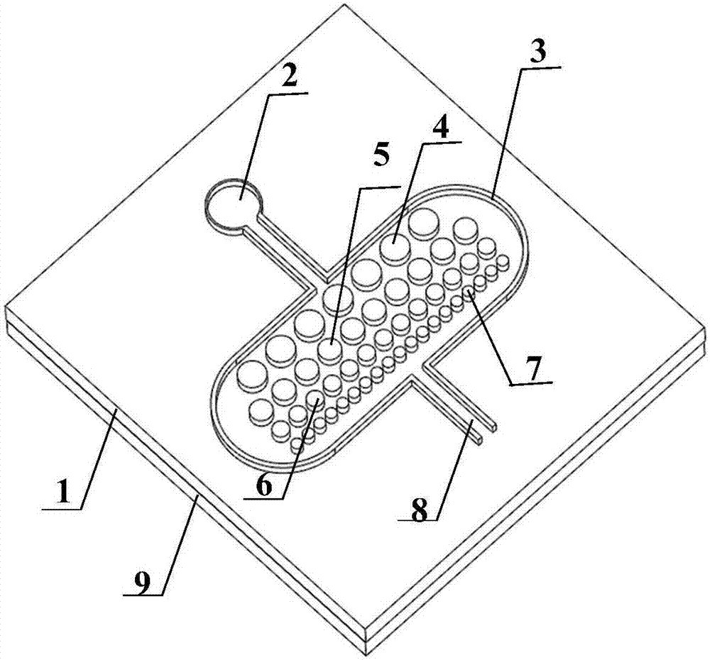
[0019] figure 1 It is a schematic diagram of the three-dimensional structure of a microchannel filter tank with a four-level decreasing pitch multi-cylindrical array structure.

[0020] Figure 4 It is a schematic diagram of the planar structure of a microchannel filter tank with a four-level decreasing pitch multi-cylindrical array structure.

[0021] A filter tank structure that blocks garbage from flowing into the microfluidic channel includes a main structure 1, a fluid inlet 2, an elliptical reservoir 3, a first-level cylindrical array structure 4, a second-level cylindrical array structure 5, and a third-level cylindrical array Structure 5, fourth-level cylindrical array structure 7, microfluidic channel 8 and lower bottom plate 9.

[0022] The fluid inlet 2, the elliptical reservoir 3, and the microfluidic channel 8 are the groove structures o...


PUM


Abstract

The invention discloses a micro-channel filter tank with four levels of spacing-decreasing multi-cylindrical array structures, and belongs to the field of microfluidic chips. The micro-channel filtertank comprises a main body channel, a liquid storage tank and the four levels of spacing-decreasing multi-cylindrical array structures. Before the multi-cylindrical array structures are sequentially arranged at a micro-channel working entrance, all substances need to go through a garbage blocking groove of the spacing-decreasing multi-cylindrical micro-channel and then can enter the micro-channel.Since the spacing of the cylindrical unit structures is extremely small, PDMS punching residues, debris generated during experiments and other solid garbage which can influence fluid in the micro-channel and are larger than cylindrical units in spacing size can be blocked. The channel structure can significantly reduce the disturbance of the punching residues, experiment garbage and the like to the normal flow of fluid in the microfluidic channel.

Description

technical field [0001] The invention relates to a multi-cylindrical microchannel filter tank with four stages of decreasing pitch, belonging to the technical field of microfluidic chips. Background technique [0002] Microfluidics is the system science and technology of manipulating micro-nano-volume samples in channels with a size of several to hundreds of microns. Usually, a biochemical analysis or detection system is built on a chip of a few square centimeters, so it is also called a chip lab. Microfluidics integrates functional units such as sample preparation, mixing, separation, reaction, and detection that are often involved in the fields of biology and chemistry. Controllable fluids run through the entire system formed by microchannels, and finally realize the same functions as conventional biochemical laboratories. Microfluidic chip technology has the advantages of small sample size, high efficiency, low cost, and easy integration, which improves people's ability to...

Claims


Application Information

Patent Timeline
IPC IPC(8): B01L3/00
CPCB01L3/502753B01L2300/0832
Inventor 刘赵淼李梦麒张龙祥
Owner BEIJING UNIV OF TECH
Why Eureka
Try Eureka