Automotive tumbrel

A motor two-wheeled vehicle and exhaust pipe technology, which is applied in the direction of motor vehicles, machines/engines, motorcycles, etc., can solve the problem of difficult to dispose of catalysts, and achieves the goal of improving disposition efficiency, reducing flow path resistance, and improving purification performance. Effect

Inactive Publication Date: 2008-05-07
HONDA MOTOR CO LTD
View PDF1 Cites 9 Cited by
  • Summary
  • Abstract
  • Description
  • Claims
  • Application Information

AI Technical Summary

Problems solved by technology

[0005] In motorcycles with a short distance from the pivot shaft 11 to the rear wheels, esp

Method used


Image

  • Automotive tumbrel
  • Automotive tumbrel
  • Automotive tumbrel

Examples


Embodiment Construction

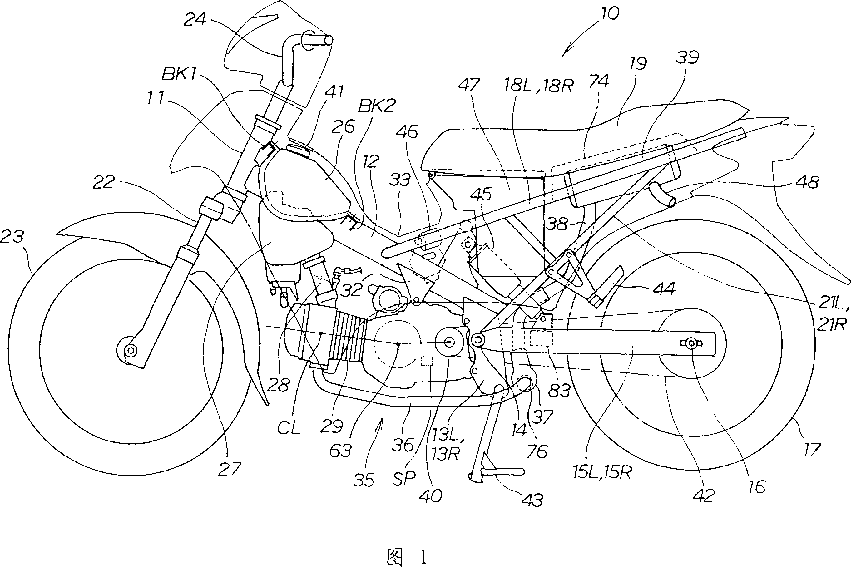
[0039] Hereinafter, preferred embodiments for carrying out the present invention will be described with reference to the drawings. The attached figure shows the situation seen from the direction indicated by the symbol. Front, rear, left, right, up, and down refer to directions based on the occupant sitting on the seat.

[0040] Fig. 1 is the side view of the motorcycle of the present invention, and the motorcycle 10 comprises: a single-beam type vehicle frame 12 extending from the head pipe 11 to the rear and downward (the right side in the figure is the rear); Pivot plates 13L, 13R (L means left, R means right; hereinafter the same) that descend from the rear end of frame 12 , pivot 14 straddling the pivot plates 13L, 13R, and pivot plate 13L via pivot 14 , 13R extend to the rear and can swing up and down rear rocker arms 15L, 15R, rear axle 16 bridged over these rear rocker arms 15L, 15R, rear wheels 17 mounted on the rear axle 16, from a single-beam vehicle Left and righ...


PUM


Abstract

The invention aims at providing a flexible tumbrel for configuring a catalyst more easily. The figure is the condition viewing from the back of the vehicle body. A beam part (37) arranged at the vehicle width direction internally arranges a cylinder catalyst (76) of the horizontal length whose length L is larger than the outside diameter D. The vent gas discharged from the front part of the vent pipe (36) flows like an arrow (1) and (2) and reaches the back part of the vent pipe(38). The back part of the vent pipe (38) passes through between a left and right rear arms (15L,15R) and through the right side of a single suspension (45) reaching a silencer (39). As the catalyst is arranged at the direction of the vehicle width without the influence of the front and back length of the vehicle body, the catalyst of the length is configured, thereby improving the purifying performance.

Description

technical field [0001] The present invention relates to the arrangement of catalysts supplied to motorcycles. Background technique [0002] In order to promote the purification of exhaust gas, a catalyst is also incorporated in the exhaust pipe of motorcycles (for example, refer to Patent Document 1). [0003] Patent Document 1: (Japanese) Unexamined Patent Publication No. 2005-220814, FIG. 1 [0004] In Fig. 1 of Patent Document 1, reference numeral 11 is a pivot, reference numeral 12 is a rear rocker arm, reference numeral 31 is an exhaust device, and reference numeral 47 is a catalyst. ) extends, in the middle of which the catalyst 47 is arranged to extend in the longitudinal direction of the vehicle body. [0005] In a motorcycle with a short distance from the pivot shaft 11 to the rear wheel, especially a small motorcycle, it is difficult to dispose the catalyst due to size restrictions. [0006] Therefore, there is a need for a motorcycle in which catalysts can be e...

Claims


Application Information

Patent Timeline
IPC IPC(8): B62K11/00F01N3/20B60K13/04B62M7/02F01N1/00F01N3/24F01N13/08
CPCY02A50/20
Inventor 井之川浩志中西孝文
Owner HONDA MOTOR CO LTD
Why Eureka
Try Eureka