

Wadding detecting method and device in core yarn spinning
A detection device and detection method technology, applied in spinning machines, jointing devices, transportation and packaging, etc.
- Summary
- Abstract
- Description
- Claims
- Application Information
AI Technical Summary
Problems solved by technology
Method used
Image

Examples
no. 1 example
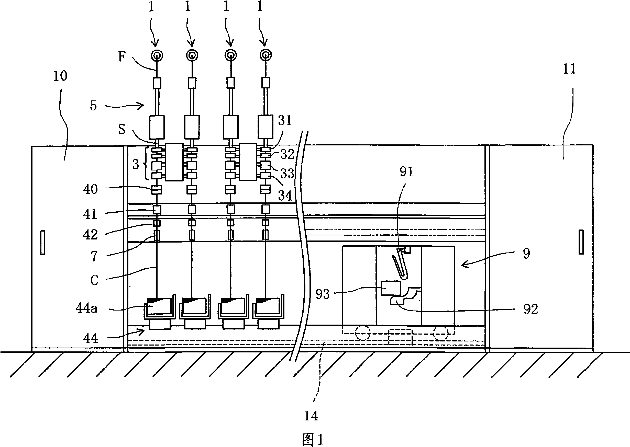
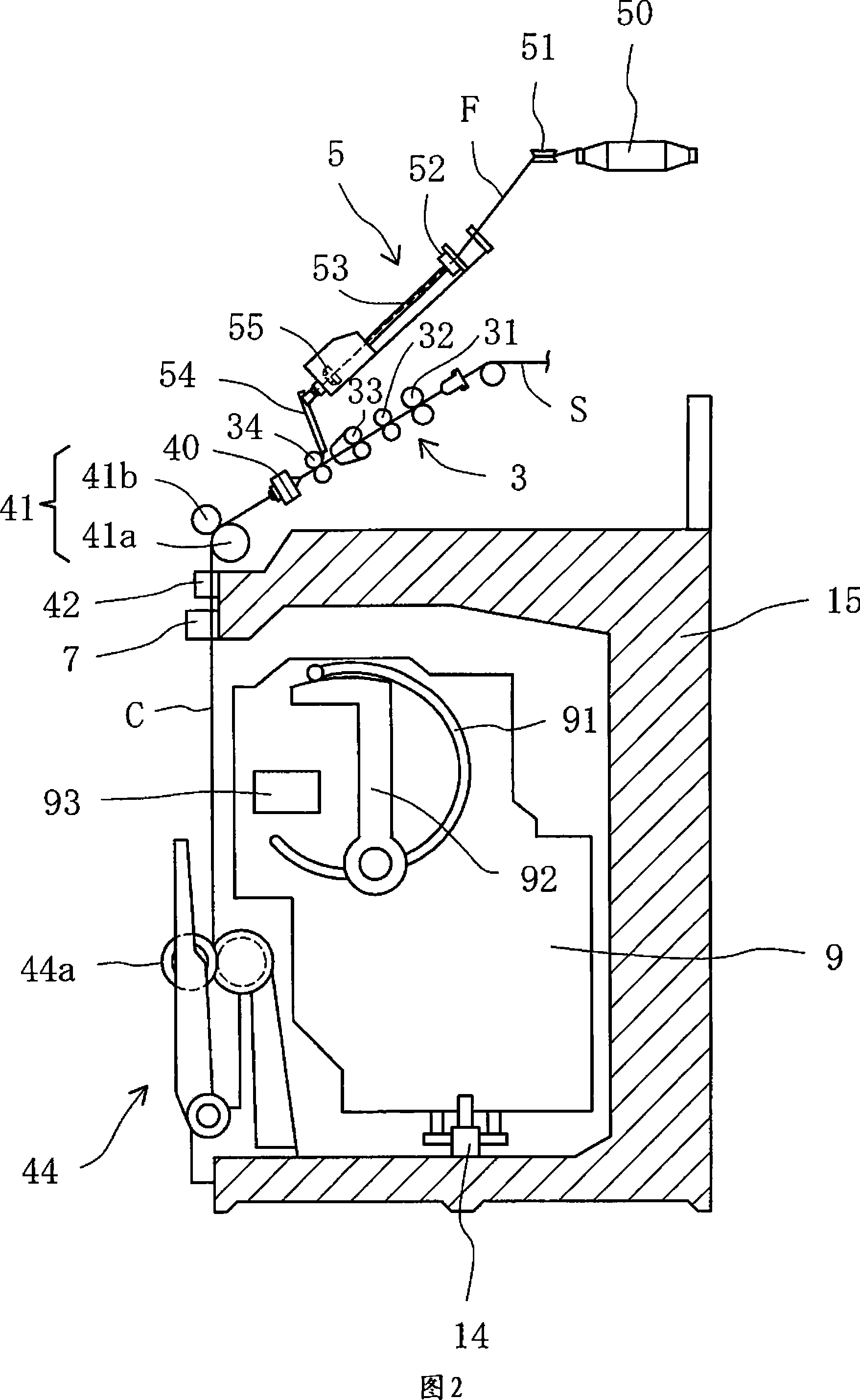
[0046] Fig. 1 is an overall front view showing the core-spun yarn spinning machine. Fig. 2 is a partial side sectional view of Fig. 1. In the core-spun yarn spinning machine, a plurality of spinning units (thread processing units) 1, 1, 1, ... are arranged in parallel between the driving box 10 and the dust collecting box 11. In addition, the core-spun yarn spinning machine is configured such that a guide rail 14 is provided along each spinning unit 1, 1, 1, ..., and the splicing platform car 9 can reciprocate in the left-right direction on the guide rail 14. Among them, the wiring platform car 9 runs and stops to the spinning unit 1 where wiring is needed to perform wiring operations.
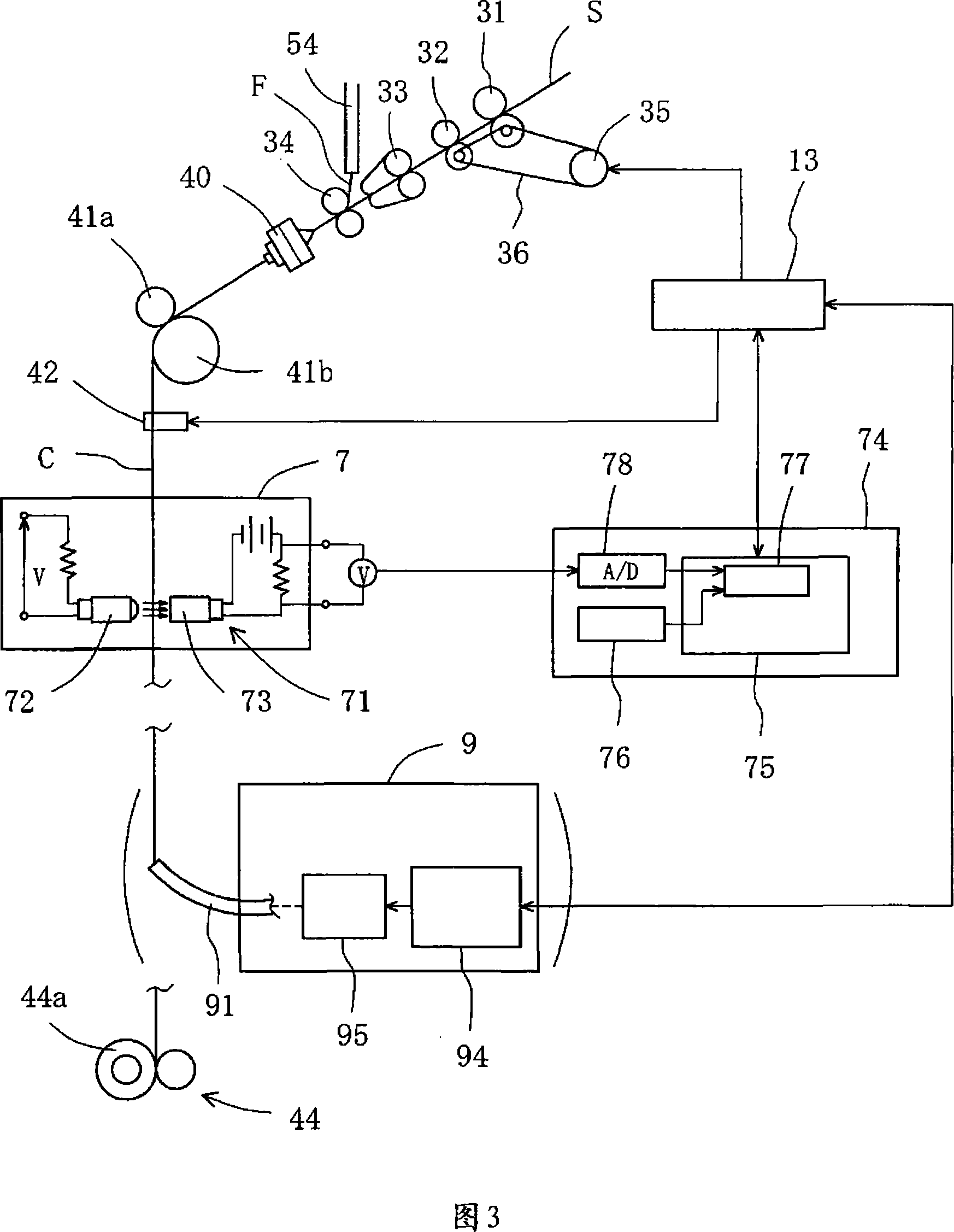
[0047] Each spinning unit 1 includes a draft device 3, a core thread supply device 5, a spinning device 40, a thread feeding device 41, and a winding device 44. The drafting device 3 has a rear roller 31, a third roller 32, a middle roller 33, and a front roller 34. The core wire supply device 5 h...
no. 2 example
[0073] Next, the second embodiment will be described. Fig. 7 is a flowchart for explaining wiring operations and the like. Since the second embodiment has a similar configuration to the first embodiment described above, only the differences will be described in detail.
[0074] In the second embodiment, the average voltage value A2 (refer to FIG. 5) of the diameter a2 of the finely counted spun yarn B without a core is measured in advance and stored in the storage unit 76. Therefore, the core-spun yarn (S1), the yarn defect detection (S2), the stop drafting device, the actuating shearing device (S3), and the running wiring platform car (S1) have been manufactured. After S4) (the same as in the first embodiment so far), the filament core yarn is supplied (S5), the draft device is driven (S6), and the finely divided core yarn C is produced (S7).
[0075] The average voltage value A1 (refer to FIG. 5) of the diameter a1 of the finely divided core-spun yarn C is input to the compariso...
no. 3 example
[0078] Hereinafter, the third embodiment will be described in detail. The description of the same parts as those of the first and second embodiments described above will be omitted. Fig. 8 is a side view of the main part of the core-spun yarn spinning machine. The core-spun yarn spinning machine of the third embodiment includes an elastic core yarn supply device 2 instead of the core yarn supply device 5 of the first and second embodiments.
[0079] The elastic core wire supply device 2 has an elastic core wire bobbin 21 and a rotating roller 22 that rotates in contact with the peripheral surface of the elastic core wire bobbin 21. The rotating roller 22 is rotated by the driving motor 24 via the belt 23. Among them, the elastic core wire bobbin 21 is rotatably supported by the bracket arm 25.
[0080] The elastic core wire D that is discharged from the elastic core wire bobbin 21 by the rotation of the rotating roller 22 passes through the supply guide tube 27 by the ejection act...
PUM
 Abstract
Description
Claims
Application Information