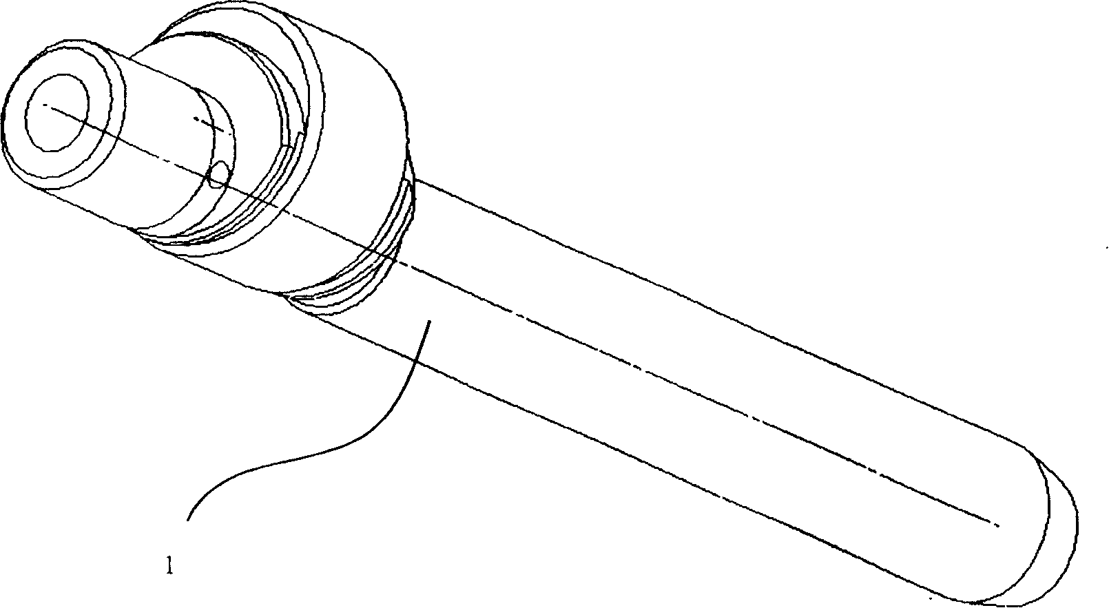
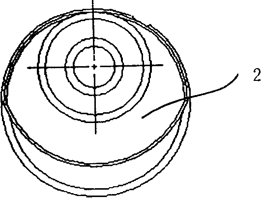
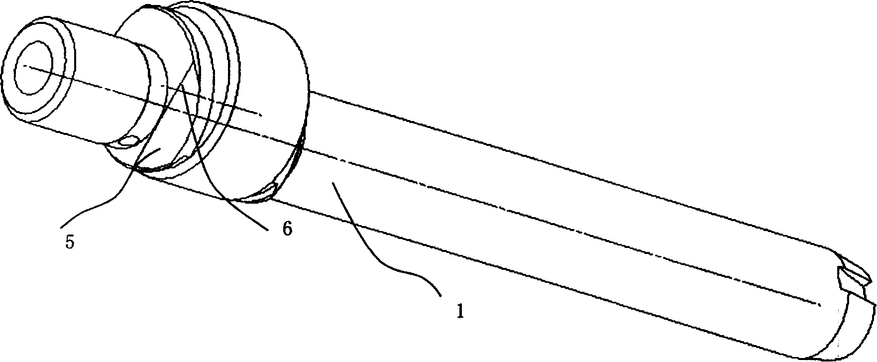
Rotor type compressor crankshaft TH face structure
A technology of compressor crankshaft and surface structure, which is applied to crankshafts, milling machine equipment details, metal processing equipment, etc., can solve problems such as reducing compressor mechanical efficiency and wasting energy, saving energy, reducing mechanical friction loss, and improving work efficiency. Effect
- Summary
- Abstract
- Description
- Claims
- Application Information
AI Technical Summary
Problems solved by technology
Method used
Image

Examples
Embodiment Construction
[0025] Ideal embodiments of the present invention that can specifically achieve the above objects will be described below with reference to the accompanying drawings. In the following description of the present embodiment, the same names and symbols are used for the parts having the same structure as the prior art, and the descriptions of these parts are omitted.
[0026] The rotary compressor of the present invention is composed of a casing, a power generation unit and a compression unit located inside the casing. The power generation part is located on the upper part of the compressor, the compression part is located on the lower part of the compressor, and the upper and lower parts of the casing are respectively equipped with a cap and a bottom cap to form a closed space inside the casing. A suction pipe for sucking the driving fluid is installed on one side of the casing, and the suction pipe is connected with a gas-liquid separator (accumulator) capable of separating lubr...
PUM
 Abstract
Description
Claims
Application Information
 - R&D
- Intellectual Property
- Life Sciences
- Materials
- Tech Scout
- Unparalleled Data Quality
- Higher Quality Content
- 60% Fewer Hallucinations
Browse by: Latest US Patents, China's latest patents, Technical Efficacy Thesaurus, Application Domain, Technology Topic, Popular Technical Reports.
© 2025 PatSnap. All rights reserved.Legal|Privacy policy|Modern Slavery Act Transparency Statement|Sitemap|About US| Contact US: help@patsnap.com