
Crank mechanisms for asymmetrical non-sinusoidal piston motion profiles in opposed piston internal combustion engines

a technology of opposed pistons and motion profiles, which is applied in the direction of combustion engines, positive displacement engines, gearing, etc., can solve the problems of lateral stress on the piston and cylinder wall, excessive vibration and noise, etc., and achieves the reduction of mechanical frictional losses, increased power output (density) of the engine, and more power strokes.

Inactive Publication Date: 2017-05-30
SNELL WILLIAM +1
View PDF4 Cites 0 Cited by
  • Summary
  • Abstract
  • Description
  • Claims
  • Application Information

AI Technical Summary

Benefits of technology

The patent describes an engine with a unique crank mechanism that helps to optimize piston motion and reduce vibrations and stresses on the engine. The engine has two opposed pistons in each cylinder, and a dual crank mechanism that works in conjunction with these pistons. The crank mechanism is designed to have an asymmetrical motion profile that matches the motion of the pistons, which helps to balance the engine and eliminate vibrations and stresses. The engine also includes a cylinder volume that is small and remains small as the exhaust gases expand, which reduces the pressure-volume loss and maximizes thermal efficiency. The asymmetric crank system design also allows for adjustment of the crank arm lengths and offsets to optimize piston motion. Overall, the engine provides improved performance and efficiency with reduced vibrations and noise.

Problems solved by technology

While only one offset crankshaft is sufficient to produce this asymmetric motion, push and pull forces normal to the piston axis may result in excess vibration and noise, as well as lateral stresses on the piston and cylinder wall.

Method used


Image

  • Crank mechanisms for asymmetrical non-sinusoidal piston motion profiles in opposed piston internal combustion engines
  • Crank mechanisms for asymmetrical non-sinusoidal piston motion profiles in opposed piston internal combustion engines
  • Crank mechanisms for asymmetrical non-sinusoidal piston motion profiles in opposed piston internal combustion engines

Examples


Embodiment Construction

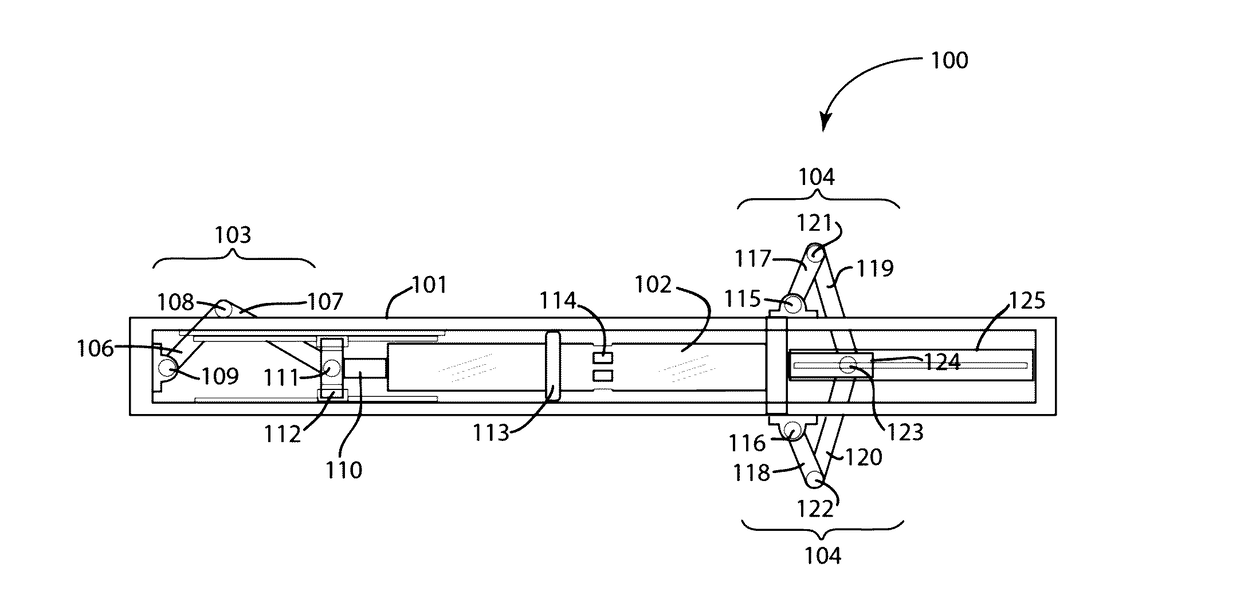
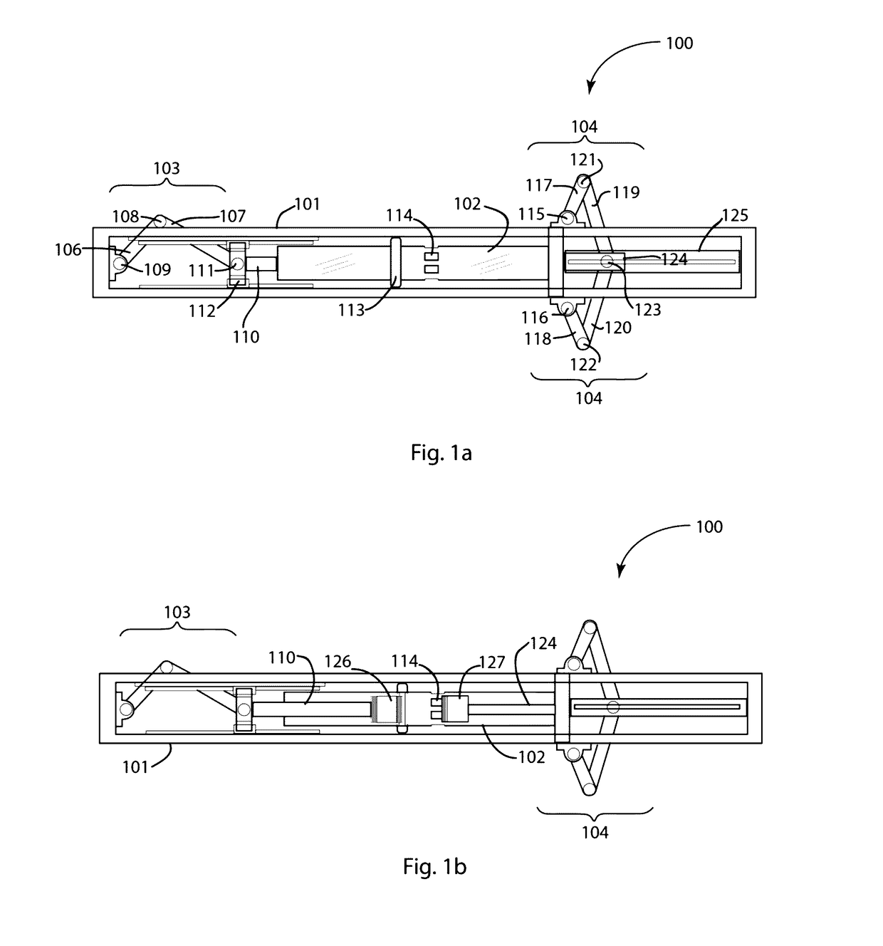
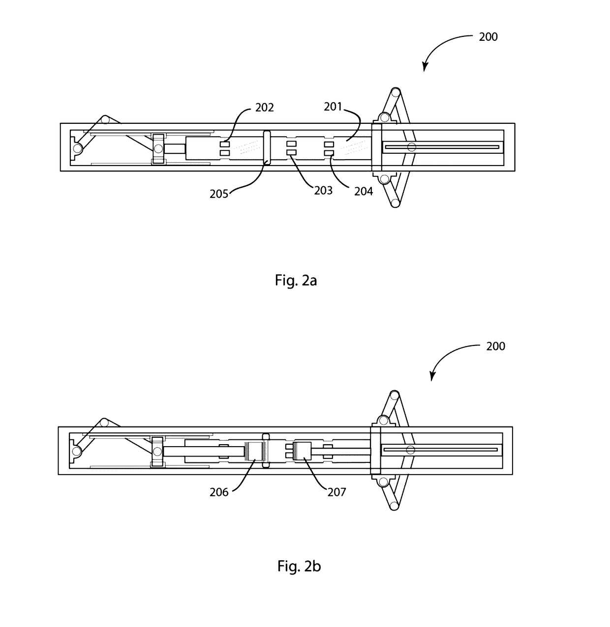
[0045]FIG. 1a schematically depicts a first single cylinder embodiment of the innovative opposed piston engine of the present disclosure. In the depiction, the engine 100 comprises structural frame 101 that supports single engine cylinder 102 serving as a common cylinder housing the opposed piston assembly is retained. For the purposes of clarity in describing the relative positions of the various engine components, inventive engine 100 may be divided into a left half and a right half. The single crank mechanism 103 of the compound crank system is shown disposed at or near the left end of cylinder 102, whereas dual crank mechanism 104 is shown disposed at or near the right end of cylinder 102. It will be understood that the reverse configuration may serve equally well for engine function. Single crank mechanism comprises crank arm 106 that is pivotally connected to linkage 107 via crank pin 108. Crank arm 106 is also affixed to engine frame 101 via articulation 109, about which it m...


PUM


Abstract

A dual crank mechanism is introduced for controlling and optimizing asymmetry in the motion profile of at least one piston of an opposed piston internal combustion (OPIC) engine piston pair. The dual crank mechanism produces a substantially asymmetrical non-sinusoidal, but periodic, reciprocating motion profile of the right-hand piston. A single crank mechanism is also introduced for controlling non-sinusoidal, but mostly symmetric, piston motion profile for one or both pistons of an opposed piston pair. The two novel crank mechanisms may be advantageously used exclusively or in combination in order to optimize the piston motion in a novel high efficiency OPIC engine having an externally mounted combustion chamber, an external compressing means for injecting compressed fuel mixtures directly into the external combustion chamber, and reducing cylinder porting to a single exhaust port per cylinder due to improved scavenging resulting from the asymmetric non-sinusoidal piston profiles produced by the novel crank mechanisms.

Description

CROSS REFERENCE TO PRIORITY APPLICATIONS[0001]This non-provisional Patent Application claims the benefit of U.S. Provisional Application No. 61 / 932,443, filed on Jan. 29, 2014; 61 / 933,575, filed on Jan. 31, 2014; 61 / 933,830, filed on Feb. 2, 2014; 61 / 934,833, filed on Feb. 2, 2014; 61 / 934,834, filed on Feb. 2, 2014; 61 / 934,841, filed on Feb. 2, 2014; 61 / 934,842, filed on Feb. 2, 2014; and 61 / 934,844, filed on Feb. 2, 2014.FIELD OF THE INVENTION[0002]This disclosure relates to opposed piston internal combustion engines, specifically their designs and methods of operationSUMMARY OF THE DISCLOSURE[0003]This disclosure describes a novel opposed piston internal combustion (IC) engine piston motion control system and method, wherein the novel engine comprises one or more cylinders arranged in a barrel configuration or in a rectilinear configuration. Each cylinder of the inventive engine houses an opposed piston pair. Each piston comprises a piston head affixed to a piston rod, wherein eac...

Claims


Application Information

Patent Timeline
Patent Type & Authority Patents(United States)
IPC IPC(8): F02B75/24F02B75/22F02B75/28F02B25/08F16H21/18F02B75/02F01B7/14
CPCF02B75/282F16H21/18F02B2075/025F02B75/246F01B7/14F02B41/06F02B75/28Y02T10/12
Inventor SNELL, WILLIAMKIRKPATRICK, SEAN
Owner SNELL WILLIAM
Learn More