Supercharge Your Innovation With Domain-Expert AI Agents!

Moisture eliminator

A dehumidifier and evaporator technology, used in household heating, lighting and heating equipment, space heating and ventilation, etc., can solve the problems of long time required, poor dehumidification effect, etc. Effects of height, reduced width and thickness

Inactive Publication Date: 2008-05-14
LG ELECTRONICS (TIANJIN) APPLIANCES CO LTD
View PDF0 Cites 22 Cited by
  • Summary
  • Abstract
  • Description
  • Claims
  • Application Information

AI Technical Summary

Problems solved by technology

However, this prior art dehumidifier has the following problems: when the indoor air is inhaled from the rear and dehumidified, it can only be discharged through the front direction, so the dehumidification effect is poor, especially when the dehumidifier is installed at a low height. The time required for uniform dehumidification of the headspace is very long

Method used


Image

  • Moisture eliminator
  • Moisture eliminator
  • Moisture eliminator

Examples


Embodiment Construction

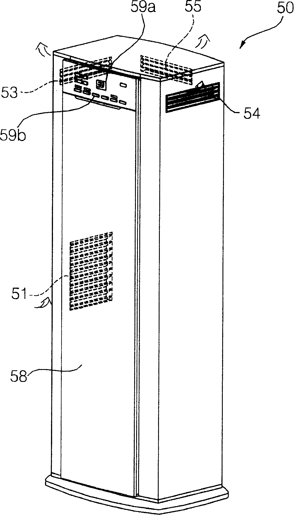
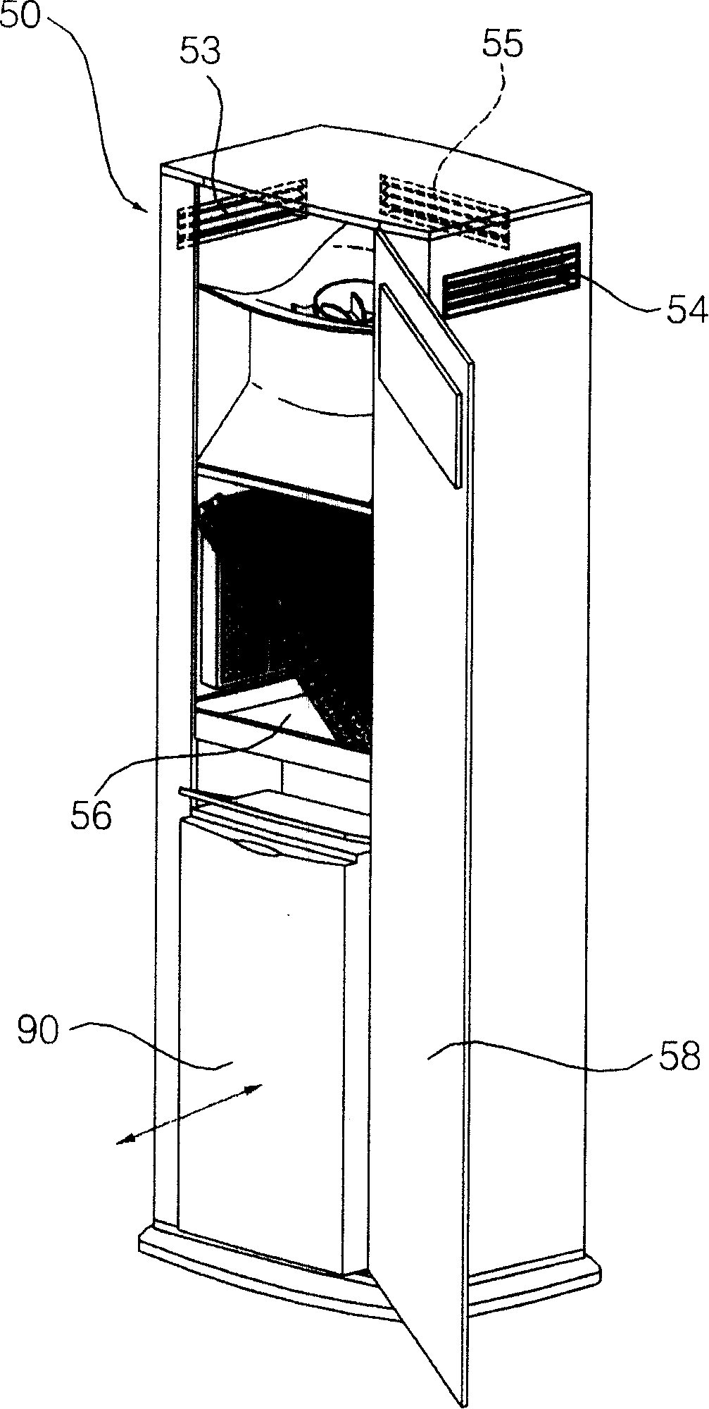
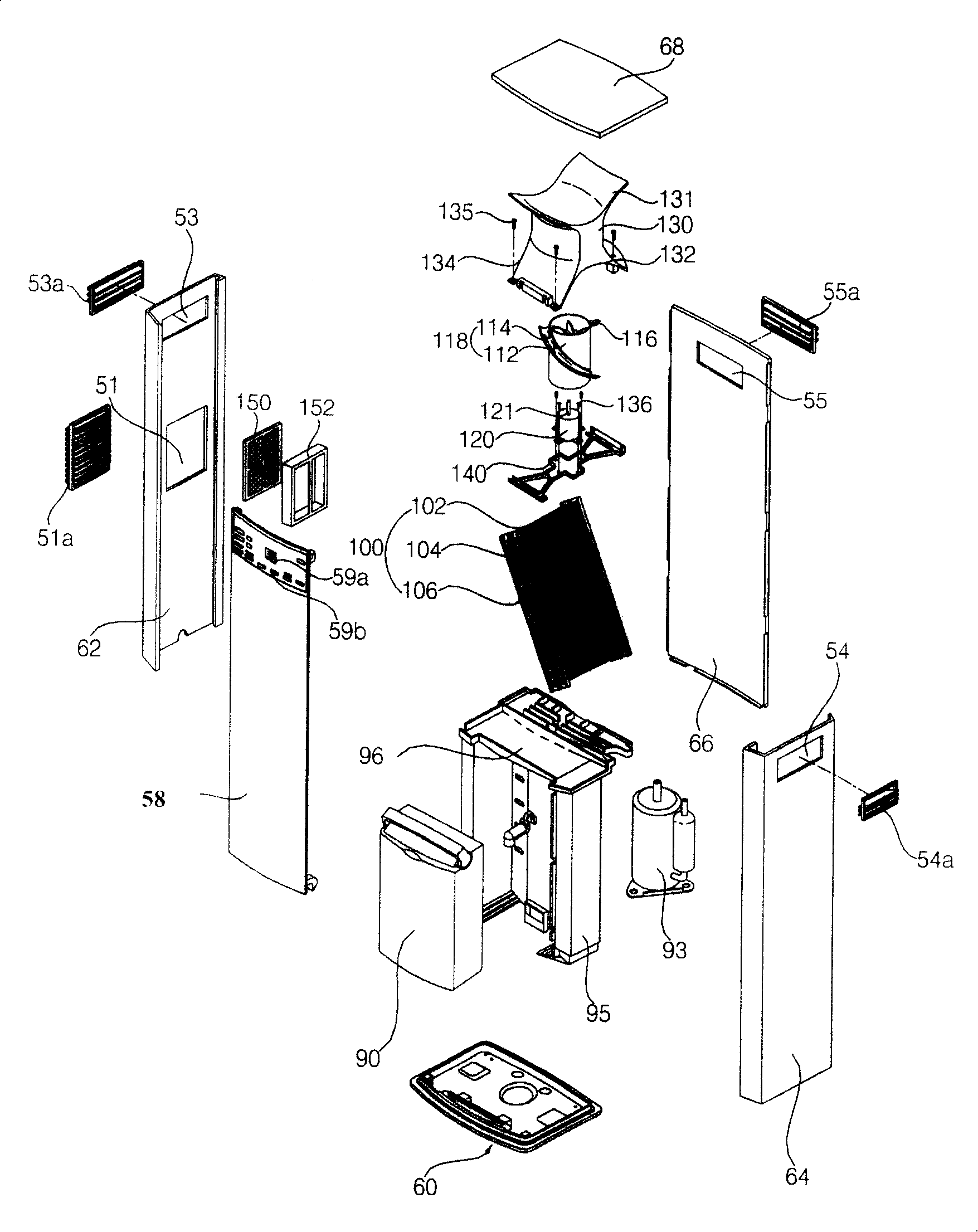
[0036] The dehumidifier provided by the present invention will be described in detail below with reference to the accompanying drawings and specific embodiments. Such as figure 1 , figure 2 As shown, the dehumidifier provided by the present invention is provided with a housing 50 forming an external structure, and the housing 50 is formed with an air suction port 51 capable of allowing indoor air to flow into its interior and an air discharge port 53 for discharging dehumidified air. 54, 55. The casing 50 is generally in the shape of a cube, and an air suction port 51 is formed at the center of any one of the left side panel and the right side panel. Hereinafter, it will be described by taking the air inlet 51 formed in the center of the left side panel as an example. In addition, a left air discharge port 53 , a right air discharge port 54 and a rear air discharge port 55 are respectively formed on the upper part of the left side panel, the upper part of the right side p...


PUM


Abstract

The invention discloses a dehumidifier, which comprises a shell that is provided with an air absorbing inlet used for the flowing in of the air and an air discharging outlet for the discharging out of the air, a heat exchanger that comprises an evaporator and a condenser and operates heat exchanging with the air flowing in from the air absorbing inlet in sequence, a wind sending fan that is positioned above the heat exchanger and comprises a hub and a plurality of vanes spirally formed along the surface of the hub, and a motor that is provided with a rotating shaft connected at the central part of the hub and is used for rotating the wind sending fan. The dehumidifier of the invention utilizes the wind sending fan arranged above the heat exchanger to discharge the air dehumidified by the heat exchanger out from a plurality of directions, thereby not only elevating the discharging height of the air, but also rapidly and evenly dehumidifying the whole indoor space. Furthermore, compared with the common axial fan or the common centrifugal fan, the wind sending fan of the invention can cause the air blown out by the wind sending fan to diffuse outwards more easily so as to rapidly discharge the dehumidified air to various directions towards the upper part of the dehumidifier.

Description

technical field [0001] The present invention relates to a dehumidifier capable of inhaling indoor air for dehumidification, and then redischarging it to the indoor space, in particular to a dehumidifier capable of inhaling indoor air for dehumidification, and then making the air flow upward and pass through the upper part in multiple directions to the dehumidifier. Exhaust dehumidifier. Background technique [0002] Figure 6 It is an exploded perspective view of the dehumidifier structure in the prior art. Figure 7 It is a cross-sectional view of the longitudinal structure of a dehumidifier in the prior art. Such as Figure 6 , Figure 7 As shown, this prior art dehumidifier includes a shell 1 that forms the left and right sides and the top surface of the dehumidifier, and the front, back and bottom surfaces are open; the evaporator 2 and the The condenser 3 is composed of a heat exchanger 4 with a dehumidification function; a compressor 10 capable of compressing the re...

Claims


Application Information

Patent Timeline
IPC IPC(8): F24F1/02
Inventor 金正勋
Owner LG ELECTRONICS (TIANJIN) APPLIANCES CO LTD
Features
  • R&D
  • Intellectual Property
  • Life Sciences
  • Materials
  • Tech Scout
  • Unparalleled Data Quality
  • Higher Quality Content
  • 60% Fewer Hallucinations
Learn More