Decoupling anti-lightning circuit and lightning protection connecting terminal

A technology of terminals and lightning protection circuits, applied in the field of decoupling lightning protection circuits and lightning protection terminals, can solve the problems of increasing electrical connection points, increasing hidden dangers of electrical faults, and large size of terminals, and reducing electrical connection points. , the effect of reducing design difficulty and improving reliability

Inactive Publication Date: 2008-05-14
深圳市威尔利实业有限公司
View PDF0 Cites 0 Cited by
  • Summary
  • Abstract
  • Description
  • Claims
  • Application Information

AI Technical Summary

Problems solved by technology

The decoupler with this structure has at least the following disadvantages: 1. The selection of the decoupler must meet the load power requirements, that is, the maximum operating current requirement. If the load increases after the lightning protection project is implemented, the decoupler should also be replaced.
2. The decoupler is a device added to the circuit, which increases the electrical connection point, that is, increases the hidden danger of electrical failure
3. The quality of the decoupler itself has a great influence on the main circuit. When higher circuit performance is required, a high-quality decoupler needs to be selected, which increases the cost
Therefore, the size of the terminal block is larger, which increases the difficulty of its design
At the same time, in order to achieve a good lightning protection effect, two or more levels of lightning protection units are often required, so it is necessary to set a decoupler between the two levels of lightning protection units. The decoupler generally uses an inductive coil or a resistor, etc. , connected in series on the line of the terminal block, increasing the electrical connection point, thus increasing the hidden danger of electrical failure

Method used


Image

  • Decoupling anti-lightning circuit and lightning protection connecting terminal
  • Decoupling anti-lightning circuit and lightning protection connecting terminal
  • Decoupling anti-lightning circuit and lightning protection connecting terminal

Examples


Embodiment Construction

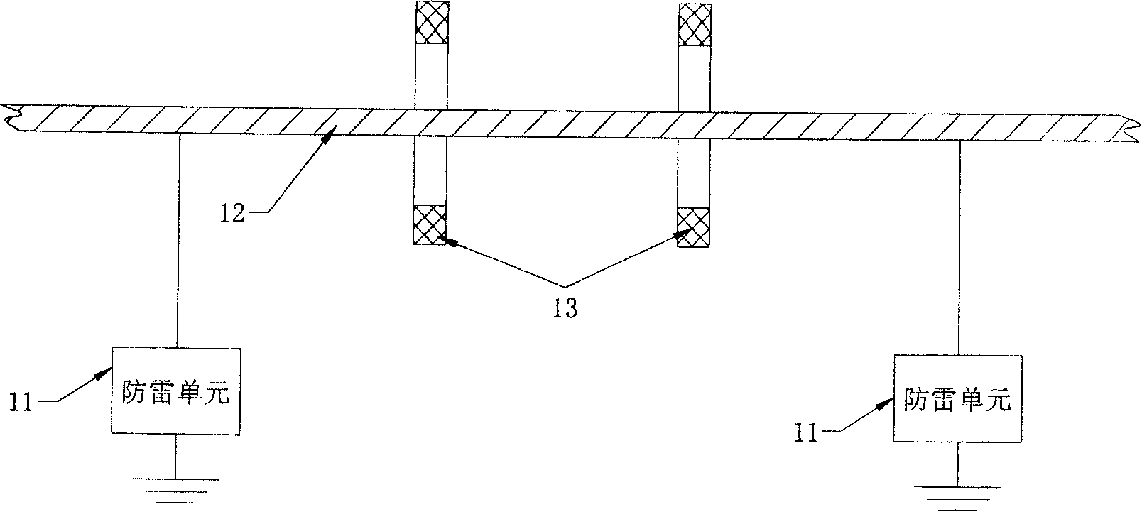
[0024] like figure 1 As shown, an embodiment of the decoupling lightning protection circuit of the present invention includes two-stage lightning protection units 11 . The lightning protection unit 11 is connected in parallel to the conductor 12 of the main circuit (not shown), so as to realize the secondary lightning protection. A decoupling unit 13 is provided between the two lightning protection units 11, and the decoupling unit 13 is a magnetic ring. The magnetic ring is sleeved on the periphery of the conductor 12 between the two-stage lightning protection units 11 . When struck by lightning and the lightning protection unit 11 works to discharge electricity, the magnetic ring generates an inductance on the conductor 12 to play a role of decoupling, so that the two-stage lightning protection unit 11 can discharge electricity well. The lightning protection unit 11 can be realized by selecting an existing lightning protection circuit.

[0025] The conductor 12 is a bare ...


PUM


Abstract

The invention relates to a decoupling lightning protection circuit and a lightning protection connection terminator. The lightning protection circuit includes at least two levels of lightning protection units which are connected to conductors of a main circuit, and the decoupling unit is arranged between the neighboring lightning protection units. The decoupling unit is at least a magnetic ring which is arranged on the outside of the conductor in the middle of the two levels lightning protection units. The connection terminator includes a connection terminator body and an anti-thunder equipment which is separated and connected with the connection terminator body. The connection terminator body includes an insulating shell, an inlet wire port and an outlet wire port arranged on two terminals of the insulating shell respectively and a conductor which is communicated with the inlet wire port and the outlet wire port. The anti-thunder equipment uses the surge lighting protection circuit. By using the magnetic ring sleeved on the outside of the conductor, the surge between the two levels lightning protection units is carried out when the lightning protection unit is operated, and the surge magnetic ring is unnecessary to have an electric connection with the conductor. Therefore, the electric connection points are reduced, and reliability of the circuit is improved.

Description

technical field [0001] The invention relates to a lightning protection device, more specifically, to a decoupling lightning protection circuit and a lightning protection terminal applying the lightning protection circuit. Background technique [0002] Lightning is a physical phenomenon that often occurs in nature. It usually refers to the discharge phenomenon of charged clouds to the earth. If electronic equipment is struck by lightning, the internal circuit will generate instantaneous overvoltage or overcurrent, which will affect the electronic equipment at least Performance, serious damage to electronic equipment will be irreversible. Therefore, in the design of electronic equipment, lightning protection design technology is usually used to reduce the impact of lightning on electronic equipment. [0003] In order to achieve a good lightning protection effect, it is generally necessary to design two or more levels of lightning protection units, and the lightning is dischar...

Claims


Application Information

Patent Timeline
Patent Type & Authority Applications(China)
IPC IPC(8): H02H9/04H01R4/30H01R13/648
Inventor 孙海元
Owner 深圳市威尔利实业有限公司
Why Eureka
Try Eureka