Automatic debugging method and system of optical module

A technology of optical module testing and optical module, applied in transmission system, transmission monitoring/testing/fault measurement system, electromagnetic wave transmission system, etc. Dependence on skilled workers, reducing the participation of human factors, and improving production efficiency

Inactive Publication Date: 2008-05-14
ZTE CORP
View PDF0 Cites 62 Cited by
  • Summary
  • Abstract
  • Description
  • Claims
  • Application Information

AI Technical Summary

Problems solved by technology

Obviously, the traditional optical module adjustment requires the debugger to be clear about the function of each adjustable potentiometer, and has high requirements for the quality of the debugger. On the other hand, the adjustment of each potentiometer inside the optical module is also very inefficient.
[0005] There are other potentiometers used for performance energy monitoring and adjustment that are not marked in the figure. Obviously, the adjustment of these mechanical potentiometers not only takes a lot of adjustment time, but also needs to clearly know the adjustment parameters corresponding to these potentiometers. In optical communication In the case of small demand in the early stage of development, the demand can be basically met
However, in recent years, with the expansion of the scale of the optical transmission network, the demand for optical modules has shown the characteristics of large one-time demand, many types of optical modules, and short delivery cycles. The production adjustment mode to manage the production of optical modules obviously cannot meet the requirements of optical communication operators. To sum up, the traditional optical module production adjustment method has the following disadvantages, including:
[0006] 1. The optical module is a technology-intensive product, which requires high quality optical module debugging technical workers, and requires a certain background knowledge of optical communication. It takes a long time to train a skilled optical module debugging technical worker
[0007] 2. The traditional optical module adjustment method is slow in adjustment speed and takes a long time, which is not suitable for the construction of sudden and large-scale optical transmission networks.
[0008] 3. Need to occupy a lot of optical module test device resources
Since there are many parameters to be monitored during the debugging of the optical module, and whether the key parameters after adjustment are accurate or not requires manual configuration of instruments to monitor, the debugging process of the optical module is bound to be accompanied by the testing process of the optical module, so it must take a long time Expensive Optical Communication Instruments
[0009] 4. Unable to realize the production management of optical modules
The traditional optical module debugging process cannot record any information about optical module debugging, so it is impossible to manage the production and debugging of batch optical modules
[0010] 5. Due to the excessive reliance on the manual debugging of skilled workers in the production of a large number of optical modules, there must be certain quality hazards. When optical modules with quality hazards are applied to the optical transmission system, it will cause major system failures, and the existence of optical modules quality defects cannot be traced
[0011] To sum up, the traditional optical module production and debugging methods can no longer meet the large-scale and sudden needs of communication operators to build optical transmission networks. Only by realizing the automatic debugging of optical modules can the adjustment speed of optical modules be accelerated and production efficiency improved. Reduce man-made quality hazards

Method used


Image

  • Automatic debugging method and system of optical module
  • Automatic debugging method and system of optical module
  • Automatic debugging method and system of optical module

Examples


Embodiment Construction

[0059] The content and functions of the present invention will be described in detail below in conjunction with the accompanying drawings and embodiments.

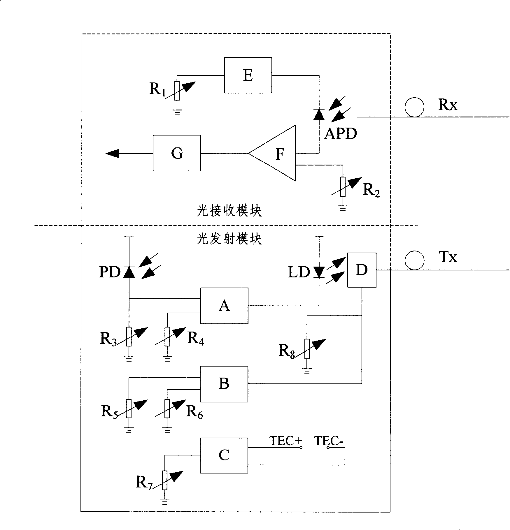
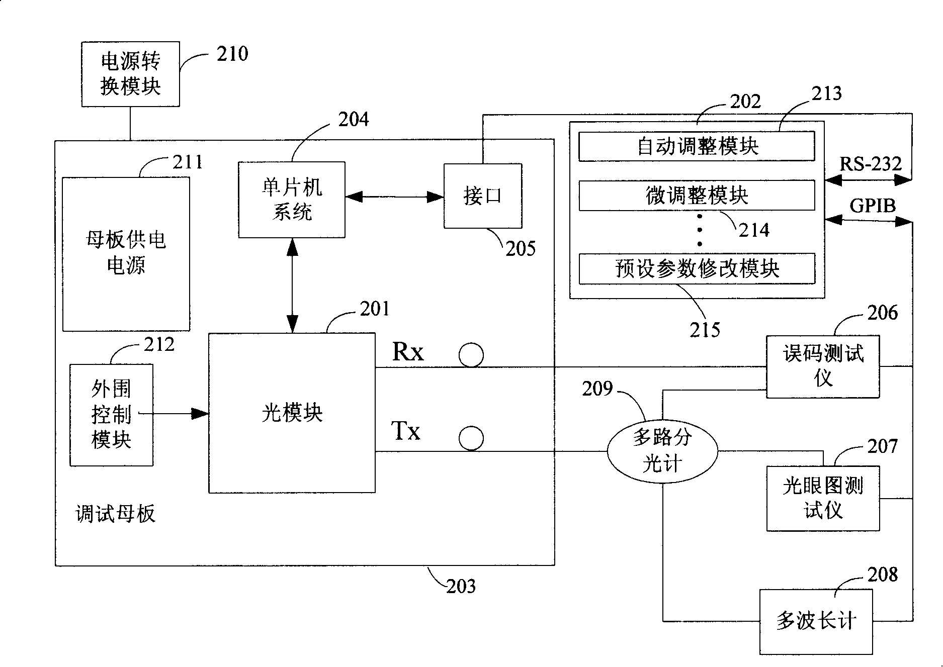
[0060] figure 2 It is a hardware system for automatic debugging of optical modules, mainly composed of optical module 201, main control computer 202, debugging motherboard 203, single-chip microcomputer system 204, interface 205, bit error tester 206, optical eye diagram tester 207, multi-wavelength meter 208, It consists of a multi-channel spectrometer 209 , a power conversion module 210 , a motherboard power supply 211 and a peripheral control module 212 .

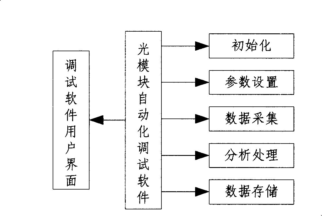
[0061] The optical module 201 to be debugged has a digital adjustment function; the main control computer 202, the optical module automatic debugging software specifically includes: an automatic adjustment module 213, a micro-adjustment module 214 and a preset parameter modification module 215, etc.; a debugging motherboard 203 Carrying the optical module 201 and o...


PUM


Abstract

The invention provides a light module automation debugging system, wherein, the invention includes: a light module, which includes a digital controller used for reporting a performance amount or an alarm amount and revising value of the digital controller corresponding to the address of key parameter of the light module r according to the digital controller instruction delivered; a main control computer, which is used for downloading a reference value of the light module and receiving an actual value reported by the light module, and then comparing the reference value to the actual value, and if the values are not equal, finds out the digital controller requiring adjustment corresponding to the address of the key parameter of the light module and delivering a numerical instruction of the revised digital controller; and a debugging motherboard, which is used for bearing the light module and is connected with the main control computer through a interface for realizing a communication between the light module and the main control computer. Furthermore, the invention also provides a method for carrying out the light module automatic debugging, thus a production efficiency of the light module debugging is improved, and artificial quality hidden dangers in the process of the debugging are reduced.

Description

technical field [0001] The invention provides an automatic debugging method and system for an optical module, and in particular relates to an automatic debugging method and system for an optical transceiver module of a high-speed optical communication system terminal photoelectric / electro-optic conversion device. Background technique [0002] The optical transceiver module includes an optical receiving module, an optical transmitting module, and an optical transceiver module. Under the condition of not realizing all-optical communication, it still plays a very important role as an important photoelectric / electro-optical conversion device in a high-speed optical communication system. In recent years, with the rapid development of optical communication technology, the types and quantities of optical modules required are also increasing rapidly. [0003] Optical communication technology is one of the emerging technical industries in the high-tech field. The installation and com...

Claims


Application Information

Patent Timeline
Patent Type & Authority Applications(China)
IPC IPC(8): H04B10/08H04B10/07
Inventor 张立昆
Owner ZTE CORP
Why Eureka
Try Eureka